Difference between revisions of "Natural Source Zone Depletion (NSZD)"
m (1 revision imported) |
|||
| (58 intermediate revisions by 3 users not shown) | |||
| Line 1: | Line 1: | ||
Natural source zone depletion (NSZD) is a term used to describe the collective, naturally occurring processes of dissolution, volatilization, and biodegradation that result in mass losses of light non-aqueous phase liquid (LNAPL) petroleum hydrocarbon constituents from the subsurface. NSZD is coming to the forefront of decision making at petroleum hydrocarbon remediation sites because much higher source attenuation rates are now being measured compared to previous rates based on incomplete conceptual models<ref>Lundegard, P.D., Johnson, P.C., 2006. Source zone natural attenuation at petroleum hydrocarbon spill sites-II: application to a former oil field. Groundwater Monitoring & Remediation, 26(4), 93-106. [http://dx.doi.org/10.1111/j.1745-6592.2006.00115.x doi:10.1111/j.1745-6592.2006.00115.x]</ref><ref name="McCoy2015">McCoy, K., Zimbron, J., Sale, T., Lyverse, M., 2015. Measurement of natural losses of LNAPL using CO<sub>2</sub> traps. Groundwater, 53(4), 658-667. [http://dx.doi.org/10.1111/gwat.12240 doi: 10.1111/gwat.12240]</ref><ref>Palaia, T. 2016. Natural Source Zone Depletion Rate Assessment. Applied NAPL Science Review (ANSR), Volume 6, Issue 1, May.</ref>. NSZD processes occur at most petroleum release sites and quantifying NSZD rates is an important part of an overall site remediation strategy. | Natural source zone depletion (NSZD) is a term used to describe the collective, naturally occurring processes of dissolution, volatilization, and biodegradation that result in mass losses of light non-aqueous phase liquid (LNAPL) petroleum hydrocarbon constituents from the subsurface. NSZD is coming to the forefront of decision making at petroleum hydrocarbon remediation sites because much higher source attenuation rates are now being measured compared to previous rates based on incomplete conceptual models<ref>Lundegard, P.D., Johnson, P.C., 2006. Source zone natural attenuation at petroleum hydrocarbon spill sites-II: application to a former oil field. Groundwater Monitoring & Remediation, 26(4), 93-106. [http://dx.doi.org/10.1111/j.1745-6592.2006.00115.x doi:10.1111/j.1745-6592.2006.00115.x]</ref><ref name="McCoy2015">McCoy, K., Zimbron, J., Sale, T., Lyverse, M., 2015. Measurement of natural losses of LNAPL using CO<sub>2</sub> traps. Groundwater, 53(4), 658-667. [http://dx.doi.org/10.1111/gwat.12240 doi: 10.1111/gwat.12240]</ref><ref>Palaia, T. 2016. Natural Source Zone Depletion Rate Assessment. Applied NAPL Science Review (ANSR), Volume 6, Issue 1, May.</ref>. NSZD processes occur at most petroleum release sites and quantifying NSZD rates is an important part of an overall site remediation strategy. | ||
<div style="float:right;margin:0 0 2em 2em;">__TOC__</div> | <div style="float:right;margin:0 0 2em 2em;">__TOC__</div> | ||
| + | |||
'''Related Article(s):''' | '''Related Article(s):''' | ||
| + | |||
*[[Monitored Natural Attenuation (MNA)]] | *[[Monitored Natural Attenuation (MNA)]] | ||
*[[Source Zone Modeling]] | *[[Source Zone Modeling]] | ||
| Line 7: | Line 9: | ||
| − | ''' | + | '''Contributor(s):''' [[Tom Palaia]], [[Jeff Fitzgibbons]] and [[Poonam Kulkarni]] |
'''Key Resource(s):''' | '''Key Resource(s):''' | ||
| − | *Quantification of Vapor Phase-Related NSZD Processes<ref>American Petroleum Institute (API). Quantification of Vapor Phase-Related NSZD Processes, | + | |
| − | *[ | + | *[https://www.crccare.com/files/dmfile/CRCCARETechnicalreport44_TechnicalmeasurementguidanceforLNAPLnaturalsourcezonedepletion.pdf Technical Measurement Guidance for LNAPL Natural Source Zone Depletion] |
| + | *Quantification of Vapor Phase-Related NSZD Processes<ref>American Petroleum Institute (API), 2017. Quantification of Vapor Phase-Related NSZD Processes, First Edition. API Publication 4784, 124 pages.</ref> | ||
| + | *[//www.enviro.wiki/images/b/bd/ITRC-2009-Nat_Zone_Depletion.pdf Evaluating Natural Source Zone Depletion at Sites with LNAPL. LNAPL-1. Washington, D.C.: Interstate Technology & Regulatory Council, LNAPLs Team.]<ref name="ITRC2009">Interstate Technology & Regulatory Council (ITRC). 2009. Evaluating Natural Source Zone Depletion at Sites with LNAPL. LNAPL-1. Washington, D.C.: Interstate Technology & Regulatory Council, LNAPLs Team. [//www.enviro.wiki/images/b/bd/ITRC-2009-Nat_Zone_Depletion.pdf Report pdf]</ref> | ||
==Introduction== | ==Introduction== | ||
| − | After a release into the environment, petroleum hydrocarbon constituents in LNAPL undergo various different degradation processes including dissolution, [[wikipedia: Volatilisation | volatilization]], and [[Biodegradation - Hydrocarbons | biodegradation]]<ref>Kostecki, P.T., E.J. Calabrese. 1989. Petroleum Contaminated Soils, Volumes 1 through 3. Lewis Publishers, Inc., Chelsea, MI.</ref><ref>National Research Council, 1993. In Situ Bioremediation - When Does It Work? Committee on In Situ Bioremediation, Water Science and Technology Board, Commission on Engineering and Technical Systems, National Academy Press, Washington D.C. [https://doi.org/10.17226/2131 doi: 10.17226/2131]</ref><ref name="NRC2000">National Research Council (NRC). 2000. Natural Attenuation for Groundwater Remediation. Washington, DC: The National Academies Press. [https://doi.org/10.17226/9792 doi: 10.17226/9792]</ref><ref name="Johnson2006">Johnson, P., Lundegard, P., Liu, Z., 2006. Source Zone Natural Attenuation at Petroleum Hydrocarbon Spill Sites-I: Site‐Specific Assessment Approach. Groundwater Monitoring & Remediation, 26(4), 82-92. [http://dx.doi.org/10.1111/j.1745-6592.2006.00114.x doi: 10.1111/j.1745-6592.2006.00114.x]</ref>. NSZD is a term used to describe these collective processes that result in mass losses of LNAPL petroleum hydrocarbon constituents from the subsurface. NSZD processes occur naturally within LNAPL-impacted zones in the subsurface. These processes physically degrade the LNAPL by mass transfer of chemical components to the aqueous and gaseous phases where they are biologically broken down via anaerobic and aerobic biodegradation. | + | After a release into the environment, petroleum hydrocarbon constituents in LNAPL undergo various different degradation processes including dissolution, [[wikipedia: Volatilisation | volatilization]], and [[Biodegradation - Hydrocarbons | biodegradation]]<ref>Kostecki, P.T., E.J. Calabrese. 1989. Petroleum Contaminated Soils, Volumes 1 through 3. Lewis Publishers, Inc., Chelsea, MI.</ref><ref>National Research Council, 1993. In Situ Bioremediation - When Does It Work? Committee on In Situ Bioremediation, Water Science and Technology Board, Commission on Engineering and Technical Systems, National Academy Press, Washington D.C. [https://doi.org/10.17226/2131 doi: 10.17226/2131]</ref><ref name="NRC2000">National Research Council (NRC). 2000. Natural Attenuation for Groundwater Remediation. Washington, DC: The National Academies Press. [https://doi.org/10.17226/9792 doi: 10.17226/9792]</ref><ref name="Johnson2006">Johnson, P., Lundegard, P., Liu, Z., 2006. Source Zone Natural Attenuation at Petroleum Hydrocarbon Spill Sites-I: Site‐Specific Assessment Approach. Groundwater Monitoring & Remediation, 26(4), 82-92. [http://dx.doi.org/10.1111/j.1745-6592.2006.00114.x doi: 10.1111/j.1745-6592.2006.00114.x]</ref>. Natural Source Zone Depletion (NSZD) is a term used to describe these collective processes that result in mass losses of LNAPL petroleum hydrocarbon constituents from the subsurface. NSZD processes occur naturally within LNAPL-impacted zones in the subsurface. These processes physically degrade the LNAPL by mass transfer of chemical components to the aqueous and gaseous phases where they are biologically broken down via anaerobic and aerobic biodegradation. |
| − | Traditional methods of NSZD monitoring have focused on the groundwater transport of the solubilized LNAPL constituents and aqueous phase biodegradation that occurs through various terminal electron acceptor processes. Aerobic respiration, [[wikipedia: Denitrification | denitrification]], sulfate reduction, iron and manganese reduction, and [[wikipedia: Methanogenesis | methanogenesis]] each support [[Biodegradation - Hydrocarbons | hydrocarbon degradation]] as the supply of each electron acceptor (e.g., dissolved oxygen, [[wikipedia: Nitrate | nitrate]], [[wikipedia: Sulfate | sulfate]]), oxidation-reduction state, and the microbiological conditions allow. These processes manifest themselves as decreases in dissolved electron acceptor concentrations and production of soluble byproducts such as ferrous iron, dissolved methane (CH<sub>4</sub>), and carbon dioxide (CO<sub>2</sub>). Through stoichiometric conversion of the mass of electron acceptor loss and byproduct formation, the soluble or aqueous contribution to NSZD can be estimated<ref name="Wiedemeier1995">Wiedemeier, T.H., Wilson, J.T., Kampbell, D.H., Miller, R.N. and Hansen, J.E., 1995. Technical Protocol for Implementing Intrinsic Remediation with Long-Term Monitoring for Natural Attenuation of Fuel Contamination Dissolved in Groundwater. U.S. Air Force Center for Environmental Excellence, Technology Transfer Division, Brooks Air Force Base, San Antonio, Texas. [ | + | Traditional methods of NSZD monitoring have focused on the groundwater transport of the solubilized LNAPL constituents and aqueous phase biodegradation that occurs through various terminal electron acceptor processes. Aerobic respiration, [[wikipedia: Denitrification | denitrification]], sulfate reduction, iron and manganese reduction, and [[wikipedia: Methanogenesis | methanogenesis]] each support [[Biodegradation - Hydrocarbons | hydrocarbon degradation]] as the supply of each electron acceptor (e.g., dissolved oxygen, [[wikipedia: Nitrate | nitrate]], [[wikipedia: Sulfate | sulfate]]), oxidation-reduction state, and the microbiological conditions allow. These processes manifest themselves as decreases in dissolved electron acceptor concentrations and production of soluble byproducts such as ferrous iron, dissolved methane (CH<sub>4</sub>), and carbon dioxide (CO<sub>2</sub>). Through stoichiometric conversion of the mass of electron acceptor loss and byproduct formation, the soluble or aqueous contribution to NSZD can be estimated<ref name="Wiedemeier1995">Wiedemeier, T.H., Wilson, J.T., Kampbell, D.H., Miller, R.N. and Hansen, J.E., 1995. Technical Protocol for Implementing Intrinsic Remediation with Long-Term Monitoring for Natural Attenuation of Fuel Contamination Dissolved in Groundwater. U.S. Air Force Center for Environmental Excellence, Technology Transfer Division, Brooks Air Force Base, San Antonio, Texas. [//www.enviro.wiki/images/f/f7/Fuels_Protocol_Monitoring_Natural_Attenuation-1.pdf Report pdf v1] [//www.enviro.wiki/images/f/f5/Fuels_Protocol_Monitoring_Natural_Attenuation-2.pdf Report pdf v2a] [//www.enviro.wiki/images/2/2f/Fuels_Protocol_Monitoring_Natural_Attenuation-2b.pdf Report pdf v2b]</ref><ref name="Newell1996">Newell, C.J., Gonzales, J., McLeod, R., 1996. BIOSCREEN natural attenuation decision support system, U.S. Environmental Protection Agency. EPA/600/R-96/087. [//www.enviro.wiki/images/3/3e/Newell-1996-Bioscreen_Natural_Attenuation_Decision_Support_System.pdf Report pdf]</ref><ref name="NRC2000" />. |
[[File:Palaia-Article 1-Figure 1.PNG|500 px|thumbnail|right]] | [[File:Palaia-Article 1-Figure 1.PNG|500 px|thumbnail|right]] | ||
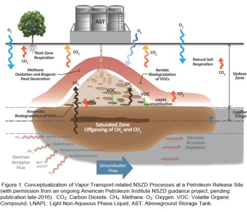
| − | Understanding of the gaseous expression of NSZD processes has recently improved via emerging research<ref name="Amos2005">Amos, R.T., Mayer, K.U., Bekins, B.A., Delin, G.N., Williams, R.L., 2005. Use of dissolved and vapor‐phase gases to investigate methanogenic degradation of petroleum hydrocarbon contamination in the subsurface. Water Resources Research, 41(2). [http://dx.doi.org/10.1029/2004wr003433 doi: 10.1029/2004WR003433]</ref><ref name="Johnson2006"/><ref name="Sihota2011">Sihota, N.J., Singurindy, O. and Mayer, K.U., 2010. CO<sub>2</sub>-efflux measurements for evaluating source zone natural attenuation rates in a petroleum hydrocarbon contaminated aquifer. Environmental Science & Technology, 45(2), 482-488. [https://doi.org/10.1021/es1032585 doi: 10.1021/es1032585]</ref><ref name="McCoy2015"/>. A large advance occurred with respect to the measurement of the significant amount of gases that can be produced because of anaerobic petroleum hydrocarbon biodegradation processes, predominantly methanogenesis<ref name="Amos2005"/>. Within the highly reduced saturated zone and overlying capillary fringe, methanogenesis occurs and generates CH<sub>4</sub> and CO<sub>2</sub>. Because of the relatively low solubility of CH<sub>4</sub>, it is subsequently transported up to the vadose zone along with smaller amounts of CO<sub>2</sub> and volatile organic compounds (VOCs). Within the vadose zone, LNAPL, CH<sub>4</sub>, and volatile hydrocarbons are anaerobically and aerobically biodegraded removing CH<sub>4</sub> and oxygen (O<sub>2</sub>) from the soil gas and adding CO<sub>2</sub>. We can conceptualize these vapor transport-related NSZD processes that are occurring at petroleum release sites | + | Understanding of the gaseous expression of NSZD processes has recently improved via emerging research<ref name="Amos2005">Amos, R.T., Mayer, K.U., Bekins, B.A., Delin, G.N., Williams, R.L., 2005. Use of dissolved and vapor‐phase gases to investigate methanogenic degradation of petroleum hydrocarbon contamination in the subsurface. Water Resources Research, 41(2). [http://dx.doi.org/10.1029/2004wr003433 doi: 10.1029/2004WR003433]</ref><ref name="Johnson2006" /><ref name="Sihota2011">Sihota, N.J., Singurindy, O. and Mayer, K.U., 2010. CO<sub>2</sub>-efflux measurements for evaluating source zone natural attenuation rates in a petroleum hydrocarbon contaminated aquifer. Environmental Science & Technology, 45(2), 482-488. [https://doi.org/10.1021/es1032585 doi: 10.1021/es1032585]</ref><ref name="McCoy2015" />. A large advance occurred with respect to the measurement of the significant amount of gases that can be produced because of anaerobic petroleum hydrocarbon biodegradation processes, predominantly methanogenesis<ref name="Amos2005" />. Within the highly reduced saturated zone and overlying capillary fringe, methanogenesis occurs and generates CH<sub>4</sub> and CO<sub>2</sub>. Because of the relatively low solubility of CH<sub>4</sub>, it is subsequently transported up to the vadose zone along with smaller amounts of CO<sub>2</sub> and volatile organic compounds (VOCs). Within the vadose zone, LNAPL, CH<sub>4</sub>, and volatile hydrocarbons are anaerobically and aerobically biodegraded removing CH<sub>4</sub> and oxygen (O<sub>2</sub>) from the soil gas and adding CO<sub>2</sub>. The biological oxidation of methane in the vadose zone is an exothermic process which releases heat to the surroundings<ref name="ITRC2018">ITRC, 2018. Light Non-Aqueous Phase Liquid (LNAPL) Site Management: LCSM Evolution, Decision Process, and Remedial Technologies. LNAPL-3. Washington, D.C. </ref><ref name="Sale2018">Sale, T. C., Stockwell, E. B., Newell, C. J., Kulkarni, P. R., 2018. Devices and Methods for Measuring Thermal Flux and Estimating Rate of Change of Reactive Material within a Subsurface Formation. U.S. Patent No. 10,094,719 filed 18 February 2015. Issued 9 October 2018.</ref>. We can conceptualize these vapor transport-related NSZD processes that are occurring at petroleum release sites as shown in Figure 1. In response to this improved understanding of NSZD, new monitoring methods have evolved to use stoichiometric conversion of the gaseous signatures left by NSZD in soil vapor or groundwater, as well as other lines of evidence such as thermal monitoring. |
| − | + | NSZD processes occurring within the subsurface manifest themselves as physical and chemical changes to both the aqueous and gaseous phases. The NSZD rate can be quantified by incorporating their petroleum hydrocarbon stoichiometric mass loss equivalents<ref name="ITRC2009" />. The methods and procedures to do this are described below. | |
==Significance== | ==Significance== | ||
Quantifying site-specific NSZD rates is important for various reasons. First, NSZD forms an important part of the LNAPL conceptual site model (LCSM), the written and/or illustrative representation of the physical, chemical, and biological processes that control the transport, migration, and actual/potential impacts of contamination. Within the LCSM, NSZD establishes a remediation baseline and supports interpretation of contaminant delineation and concentration trends. NSZD measurements can be used to: | Quantifying site-specific NSZD rates is important for various reasons. First, NSZD forms an important part of the LNAPL conceptual site model (LCSM), the written and/or illustrative representation of the physical, chemical, and biological processes that control the transport, migration, and actual/potential impacts of contamination. Within the LCSM, NSZD establishes a remediation baseline and supports interpretation of contaminant delineation and concentration trends. NSZD measurements can be used to: | ||
| + | |||
*Refine the LCSM with quantification of LNAPL loss rates | *Refine the LCSM with quantification of LNAPL loss rates | ||
*Delineate the LNAPL footprint using vadose zone indicators of biodegradation | *Delineate the LNAPL footprint using vadose zone indicators of biodegradation | ||
*Support estimates of remedial timeframes | *Support estimates of remedial timeframes | ||
*Assess LNAPL stability through application of a mass balance of losses and measured mobile LNAPL flux<ref>Mahler, N., Sale, T., Lyverse, M., 2012. A mass balance approach to resolving LNAPL stability. Groundwater, 50(6), 861-871. [http://dx.doi.org/10.1111/j.1745-6584.2012.00949.x doi: 10.1111/j.1745-6584.2012.00949.x]</ref> | *Assess LNAPL stability through application of a mass balance of losses and measured mobile LNAPL flux<ref>Mahler, N., Sale, T., Lyverse, M., 2012. A mass balance approach to resolving LNAPL stability. Groundwater, 50(6), 861-871. [http://dx.doi.org/10.1111/j.1745-6584.2012.00949.x doi: 10.1111/j.1745-6584.2012.00949.x]</ref> | ||
| + | |||
Measured NSZD rates can also form the basis for [[Remediation Technologies | remediation technology]] selection, design, and optimization. For example: | Measured NSZD rates can also form the basis for [[Remediation Technologies | remediation technology]] selection, design, and optimization. For example: | ||
| + | |||
*Comparing LNAPL mass removal rates from NSZD to other future potential remedial actions | *Comparing LNAPL mass removal rates from NSZD to other future potential remedial actions | ||
*Supporting a cost/benefit analysis of future remediation by evaluating the value of additional remediation compared to NSZD | *Supporting a cost/benefit analysis of future remediation by evaluating the value of additional remediation compared to NSZD | ||
| Line 40: | Line 47: | ||
==Measuring the NSZD Aqueous Expression== | ==Measuring the NSZD Aqueous Expression== | ||
| − | NSZD is quantified by | + | NSZD is quantified by assuming the petroleum hydrocarbon stoichiometric equivalent of biodegradation expresses itself by changes in both the aqueous (soluble) and gaseous (vapor) phases<ref name="ITRC2009" />. This section covers the aqueous component. Within the saturated zone, aerobic respiration, denitrification, sulfate reduction, iron and manganese reduction, and methanogenesis each support hydrocarbon degradation and LNAPL mass loss. |
| − | |||
| − | |||
| − | |||
| − | [[File:Palaia-Article 1-Table 1.PNG|900px|thumbnail| | + | [[File:Palaia-Article 1-Table 1.PNG|900px|thumbnail|left|Table 1. Terminal electron accepting processes associated with the aqueous expression of NSZD (for decane, excerpt from Johnson et al. (2006)<ref name="Johnson2006" />).]] |
| + | [[File: NSZD2019Fig2a.png |thumb|350px| Figure 2a. [http://www.isotechlabs.com/products/isoflask/ IsoFlask] Sampling Protocol.]] | ||
| + | [[File: NSZD2019Fig2b.png |thumb|350px| Figure 2b. IsoFlask dissolved gas sampling results for LNAPL-impacted (triangles) and background (circle) locations.]] | ||
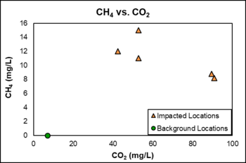
| + | For example, nitrate, iron, sulfate, and manganese reduction are some of the representative reactions for each process (Table 1). These processes manifest themselves as decreases in dissolved electron acceptor concentrations and production of soluble byproducts such as ferrous iron and dissolved CH<sub>4</sub> and CO<sub>2</sub>. The soluble or aqueous contribution to NSZD can be estimated through stoichiometric conversion of the mass of electron acceptor loss and byproduct formation<ref name="Wiedemeier1995" /><ref name="NRC2000" />. Because these estimates can be made using conventional groundwater sampling and analytical methods, the saturated zone component of NSZD is relatively well understood, and well-established procedures have been in place for over 20 years to monitor the NSZD process. However, conventional sampling programs often use open-system sample collection methods in which the sample is in direct contact with the atmosphere (e.g., direct fill and inverted VOA sampling methods). If the groundwater has elevated dissolved gas concentrations, some fraction of those gases may be lost to the atmosphere during sample collection. | ||
| + | The IsoFlask methodology (Figure 2a) uses a closed system where both dissolved and effervescing gases are captured and measured in the laboratory, which may provide more accurate results of dissolved gas analysis<ref>Molofsky, L.J., Richardson, S.D., Gorody, A.W., Baldassare, F., Black, J.A., McHugh, T.E. and Connor, J.A., 2016. Effect of different sampling methodologies on measured methane concentrations in groundwater samples. Groundwater, 54(5), pp.669-680. [https://doi.org/10.1111/gwat.12415 doi: 10.1111/gwat.12415]</ref>. As seen in Figure 2b, results from an NSZD site evaluation indicated higher methane and carbon dioxide dissolved gas concentrations in the LNAPL-impacted locations as compared to the clean, background location. | ||
| − | The aqueous contribution to NSZD, historically known as the microbiological natural attenuation rate or assimilative capacity, is typically calculated using a mass budgeting approach<ref name="NRC2000"/>. The mass budgeting approach estimates dissolved hydrocarbon constituent losses within the saturated zone based on changes in the aforementioned electron acceptors and byproducts across transects through the hydrocarbon plume that spans upgradient and downgradient areas. Changes in concentrations for each process are stoichiometrically converted to hydrocarbon losses using the coefficients in Table 1. Groundwater models such as BIOSCREEN combine this mass budgeting approach with an [[Advection and Groundwater Flow | advection]] [[Dispersion and Diffusion | dispersion]] model<ref name="Newell1996"/>. | + | The aqueous contribution to NSZD, historically known as the microbiological natural attenuation rate or assimilative capacity, is typically calculated using a mass budgeting approach<ref name="NRC2000" />. The mass budgeting approach estimates dissolved hydrocarbon constituent losses within the saturated zone based on changes in the aforementioned electron acceptors and byproducts across transects through the hydrocarbon plume that spans upgradient and downgradient areas. Changes in concentrations for each process are stoichiometrically converted to hydrocarbon losses using the coefficients in Table 1. Groundwater models such as BIOSCREEN combine this mass budgeting approach with an [[Advection and Groundwater Flow | advection]] [[Dispersion and Diffusion | dispersion]] model<ref name="Newell1996" />. |
==Measuring the NSZD Gaseous Expression== | ==Measuring the NSZD Gaseous Expression== | ||
| − | Current NSZD practice is to evaluate the petroleum hydrocarbon stoichiometric equivalent of biodegradation in both the aqueous phase and gaseous (vapor) phase<ref name="ITRC2009"/>. This section covers the gaseous component | + | Current NSZD practice is to evaluate the petroleum hydrocarbon stoichiometric equivalent of biodegradation in both the aqueous phase and gaseous (vapor) phase<ref name="ITRC2009" />. This section covers the gaseous component. |
| − | |||
| − | |||
| − | + | At one site, the gaseous expression of NSZD has been shown to account for >70% of the hydrocarbon biodegradation that occurs in the subsurface<ref>Molins, S., Mayer, K.U., Amos, R.T., Bekins, B.A., 2010. Vadose zone attenuation of organic compounds at a crude oil spill site - Interactions between biogeochemical reactions and multicomponent gas transport. Journal of Contaminant Hydrology, 112(1), 15-29. [http://dx.doi.org/10.1016/j.jconhyd.2009.09.002 doi: 10.1016/j.jconhyd.2009.09.002]</ref><ref name="Ng et al 2015">Ng, G-H.C., Bekins, B.A., Cozzarelli, I.M., Baedecker, M.J., Bennett, P.C., Amos, R.T., Herkelrath, W.N., 2015. Reactive transport modeling of geochemical controls on secondary water quality impacts at a crude oil spill site near Bemidji, MN. Water Resources Research, (51) pp 4156–4183. [http://dx.doi.org/10.1002/2015wr016964 doi:10.1002/2015WR016964][//www.enviro.wiki/images/6/6c/Ng_et_al_2015.pdf report.pdf]</ref>. Three methods to monitor the vapor phase-related portion of NSZD are currently available and widely used. These are the gradient, passive flux trap, and dynamic closed chamber (DCC) methods elaborated on below. Method choice for a particular project is a site-specific judgment based on data quality, monitoring objectives, and site conditions. | |
| + | [[File:Palaia-Article 1-Figure 2.PNG|450px|thumbnail|Figure 2c. Schematic of a typical gradient method monitoring setup (excerpt from Johnson et al. (2006)<ref name="Johnson2006" />).]] | ||
===Gradient Method=== | ===Gradient Method=== | ||
| Line 62: | Line 69: | ||
<div align="center">[[File:Palaia-Article 1-Equation 1.PNG]]</div> | <div align="center">[[File:Palaia-Article 1-Equation 1.PNG]]</div> | ||
| − | where [[File:Palaia-Article 1-Fraction 1.1.PNG|40 px]] is the effective diffusion coefficient of the gas of interest in the vadose zone soils, and [[File:Palaia-Article 1-Fraction 1.2.PNG|25 px]] is the vertical concentration gradient of the gas being used to estimate NSZD rates. The gas flux is then stoichiometrically converted to an NSZD rate. This gradient method was the first published method to estimate NSZD<ref name="Johnson2006"/> | + | where [[File:Palaia-Article 1-Fraction 1.1.PNG|40 px]] is the effective diffusion coefficient of the gas of interest in the vadose zone soils, and [[File:Palaia-Article 1-Fraction 1.2.PNG|25 px]] is the vertical concentration gradient of the gas being used to estimate NSZD rates. The gas flux is then stoichiometrically converted to an NSZD rate. This gradient method was the first published method to estimate NSZD<ref name="Johnson2006" />. |
| − | |||
| − | |||
| − | + | A typical gradient method NSZD monitoring setup primarily includes a nested set of soil vapor probes installed above the LNAPL-impacted soils (Figure 2c). Soil gas samples are collected from the probes using industry-standard procedures and analyzed using a field landfill gas meter (e.g., LANDTEC GEM2000). | |
| − | + | Two key elements to implementing the gradient method include selection of the depth intervals for calculating '''''<sup>dC</sup>/<sub>dz</sub>''''' and estimation of ''D<sub>v</sub><sup>eff</sup>''. The gradient can be estimated in a linear manner, using two points, and include the ground surface and atmospheric conditions as the upper control point. The lower control point is ideally situated immediately above the hydrocarbon oxidation zone, where oxygen is depleted and methane is absent. While literature values of ''D<sub>v</sub><sup>eff</sup>'' could be used in a screening application of the gradient method, it is best to either empirically estimate the parameter using Millington and Quirk (1961)<ref>Millington, R.J., Quirk, J.M., 1961. Permeability of porous solids. Transaction of the Faraday Society 57, 1200–1207.</ref> or measure it directly<ref>Johnson, P.C., C. Bruce, R.L. Johnson, Kemblowski, M.W., 1998. In situ measurement of effective vapor-phase porous medium diffusion coefficients. Environmental Science & Technology, 32(21), 3405–3409. [http://pubs.acs.org/doi/abs/10.1021/es980186q doi: 10.1021/es980186q]</ref>. | |
===Passive Flux Trap=== | ===Passive Flux Trap=== | ||
| − | A passive flux trap is a flow-through, static chamber fitted with a chemical trap that has historically been used to measure soil-surface CO<sub>2</sub> efflux<ref>Humfeld, H. 1930. A Method for Measuring Carbon Dioxide Evolution from Soil. Soil Science, Vol. 30(1), pp: 1-12.</ref>. The passive flux trap method was recently adapted for NSZD monitoring<ref name="McCoy2015"/> and subsequently commercialized and further refined by [http://www.soilgasflux.com/main/home.php E-Flux, LLC] in Fort Collins, Colorado. The E-Flux CO<sub>2</sub> trap employs the use of a dual-sorbent design to collect CO<sub>2</sub> leaving the subsurface ( | + | [[File:Palaia-Article 1-Figure 3.PNG|500px|thumbnail|left|Figure 3a. Schematic (left) and photo (right) of a passive CO<sub>2</sub> Flux Trap (Used with permission from E-Flux, LLC. [http://www.soilgasflux.com Soil Gas Flux])]][[File: GSI_Carbon_Trap_Short_Video_Wiki_v2.mp4 |450px|thumbnail|Figure 3b. How Carbon Traps Work.]] |
| − | + | A passive flux trap is a flow-through, static chamber fitted with a chemical trap that has historically been used to measure soil-surface CO<sub>2</sub> efflux<ref>Humfeld, H. 1930. A Method for Measuring Carbon Dioxide Evolution from Soil. Soil Science, Vol. 30(1), pp: 1-12.</ref>. The passive flux trap method was recently adapted for NSZD monitoring<ref name="McCoy2015" /> and subsequently commercialized and further refined by [http://www.soilgasflux.com/main/home.php E-Flux, LLC] in Fort Collins, Colorado. The E-Flux CO<sub>2</sub> trap employs the use of a dual-sorbent design to collect CO<sub>2</sub> leaving the subsurface (Figure 3a). Although other configurations are possible, the trap is typcally installed in the shallow ground surface (i.e., 1–3 inches deep) and left in place for a 1–2 week timeframe. Over this time, CO<sub>2</sub> derived from LNAPL degradation (i.e., fossil fuel-derived CO<sub>2</sub>) migrating upward from the subsurface to the atmosphere is collected inside the receiver pipe by a bottom caustic sorbent element. An upper sorbent element captures atmospheric CO<sub>2</sub> (i.e., modern CO<sub>2</sub>) to avoid cross-contamination of the lower sorbent element, which is solely used for the NSZD estimate. The trap is deployed for a period of time that does not allow for either the top or bottom elements to become saturated with CO<sub>2</sub>. After the deployment period, the trap is retrieved and shipped to a laboratory for analysis of CO<sub>2</sub>. The CO<sub>2</sub> efflux is estimated by dividing the trip blank-corrected mass of CO<sub>2</sub> sorbed on the lower element by the deployment duration and the cross sectional area of the received pipe. Finally, a <sup>14</sup>C correction is employed to separate the flux of modern CO<sub>2</sub> flux (such as from decay of vegetation) from the “ancient” CO<sub>2</sub> flux (from the biodegradation of petroleum products). For a more detailed explanation see the video “How Carbon Traps Work” (Figure 3b). | |
| − | |||
===Dynamic Closed Chamber (DCC) Method=== | ===Dynamic Closed Chamber (DCC) Method=== | ||
| − | [[File:Palaia-Article 1-Figure 4.PNG|500px| | + | [[File:Palaia-Article 1-Figure 4.PNG|500px|thumb]] |
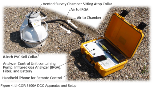
| − | A DCC system is an active, specially adapted, direct measurement approach to estimate soil gas efflux at the ground surface. It pumps a small, closed loop circulation of air between a chamber set on a soil collar shallowly embedded in the ground surface and an external non-destructive gas analyzer that monitors the increase in CO<sub>2</sub> concentration. To minimize errors associated with pressure differential inside and outside of the chamber, it is fitted with an engineered vent. DCC has been demonstrated to be a consistent efflux measurement method and used as reference for comparison to others<ref>Norman, J.M., Kucharik, C.J., Gower, S.T., Baldocchi, D.D., Crill, P.M., Rayment, M., Savage, K., Strieglfi, R.G., 1997. A comparison of six methods for measuring soil-surface carbon dioxide fluxes. Journal of Geophysical Research, 102(D24), 28771–28777. [http://dx.doi.org/10.1029/97jd01440 doi: 10.1029/97JD01440]</ref>. The DCC has been used primarily for ecological carbon monitoring purposes and was recently adapted for NSZD monitoring<ref name="Sihota2011"/>. Figure 4 shows an example DCC system, the LI-COR® 8100A automated soil flux system (LI-COR® BioSciences, Inc., Lincoln, Nebraska), and its typical setup for NSZD monitoring. | + | A DCC system is an active, specially adapted, direct measurement approach to estimate soil gas efflux at the ground surface. It pumps a small, closed loop circulation of air between a chamber set on a soil collar shallowly embedded in the ground surface and an external non-destructive gas analyzer that monitors the increase in CO<sub>2</sub> concentration. To minimize errors associated with pressure differential inside and outside of the chamber, it is fitted with an engineered vent. DCC has been demonstrated to be a consistent efflux measurement method and used as reference for comparison to others<ref>Norman, J.M., Kucharik, C.J., Gower, S.T., Baldocchi, D.D., Crill, P.M., Rayment, M., Savage, K., Strieglfi, R.G., 1997. A comparison of six methods for measuring soil-surface carbon dioxide fluxes. Journal of Geophysical Research, 102(D24), 28771–28777. [http://dx.doi.org/10.1029/97jd01440 doi: 10.1029/97JD01440]</ref>. The DCC has been used primarily for ecological carbon monitoring purposes and was recently adapted for NSZD monitoring<ref name="Sihota2011" />. Figure 4 shows an example DCC system, the LI-COR® 8100A automated soil flux system (LI-COR® BioSciences, Inc., Lincoln, Nebraska), and its typical setup for NSZD monitoring. |
| − | Using an internal pump, the DCC system circulates vapor that has accumulated within the chamber through a closed loop. Through continuous circulation and in-line measurement of the CO<sub>2</sub> concentration by the non-destructive infrared gas analyzer (IRGA), the temporal increase in CO<sub>2</sub> is recorded. The CO<sub>2</sub> efflux is estimated using a curve fitting routine on the time series CO<sub>2</sub> concentration data and dividing the results by the cross sectional area of the soil collar. The DCC collects rapid CO<sub>2</sub> efflux measurements over a period of ~ 2 minutes. A series of multiple measurements are typically recorded during each field event. A long-term DCC system is also commercially available for automated, repeated measurement programs<ref>Sihota, N.J., Trost, J.J., Bekins, B.A., Berg, A., Delin, G.N., Mason, B., Warren, E., Mayer, K.U., 2016. Seasonal Variability in Vadose Zone Biodegradation at a Crude Oil Pipeline Rupture Site. Vadose Zone Journal,15(5). [https://doi.org/10.2136/vzj2015.09.0125 doi:10.2136/vzj2015.09.0125]</ref><ref>LI-COR Chambers. 2016. Accessed by https://www.licor.com/env/products/soil_flux/chambers.html. October 2016. [ | + | Using an internal pump, the DCC system circulates vapor that has accumulated within the chamber through a closed loop. Through continuous circulation and in-line measurement of the CO<sub>2</sub> concentration by the non-destructive infrared gas analyzer (IRGA), the temporal increase in CO<sub>2</sub> is recorded. The CO<sub>2</sub> efflux is estimated using a curve fitting routine on the time series CO<sub>2</sub> concentration data and dividing the results by the cross sectional area of the soil collar. The DCC collects rapid CO<sub>2</sub> efflux measurements over a period of ~ 2 minutes. A series of multiple measurements are typically recorded during each field event. A long-term DCC system is also commercially available for automated, repeated measurement programs<ref>Sihota, N.J., Trost, J.J., Bekins, B.A., Berg, A., Delin, G.N., Mason, B., Warren, E., Mayer, K.U., 2016. Seasonal Variability in Vadose Zone Biodegradation at a Crude Oil Pipeline Rupture Site. Vadose Zone Journal,15(5). [https://doi.org/10.2136/vzj2015.09.0125 doi:10.2136/vzj2015.09.0125]</ref><ref>LI-COR Chambers. 2016. Accessed by https://www.licor.com/env/products/soil_flux/chambers.html. October 2016. [//www.enviro.wiki/images/e/e7/LI-COR-2016_Webpage.pdf Report pdf]</ref>. |
==Gaseous Flux Background Correction== | ==Gaseous Flux Background Correction== | ||
| − | The gaseous expression of NSZD is complicated by concurrent, non-petroleum related processes that also consume O<sub>2</sub> and create CO<sub>2</sub><ref>Rochette, P., Hutchinson, G.L., 2005. Measurement of soil respiration in situ: chamber techniques. Publications from USDA-ARS / UNL Faculty. Paper 1379. [ | + | The gaseous expression of NSZD is complicated by concurrent, non-petroleum related processes that also consume O<sub>2</sub> and create CO<sub>2</sub><ref>Rochette, P., Hutchinson, G.L., 2005. Measurement of soil respiration in situ: chamber techniques. Publications from USDA-ARS / UNL Faculty. Paper 1379. [//www.enviro.wiki/images/6/6d/Rochette-2005-Soil_Respiration.pdf Report pdf]</ref>. These “background” processes include contributions from plant roots and microbes present in surficial and deeper soils containing natural organic matter. Therefore, correction is needed to subtract these effects prior to using the data from the gradient method and the two CO<sub>2</sub> efflux methods (i.e., trap and DCC) for NSZD estimates. Options to eliminate the gaseous contributions of non-petroleum related sources include: |
| + | |||
*Install measurement locations in a nearby uncontaminated setting with similar surface and subsurface conditions. Calculation of NSZD rates using this approach involves subtracting the gaseous flux measured at the background location from the total flux at each survey location atop the LNAPL footprint. | *Install measurement locations in a nearby uncontaminated setting with similar surface and subsurface conditions. Calculation of NSZD rates using this approach involves subtracting the gaseous flux measured at the background location from the total flux at each survey location atop the LNAPL footprint. | ||
| − | *Use radiocarbon-14 (<sup>14</sup>C) analysis on the CO<sub>2</sub> collected from either the soil gas probes (gradient method) or the passive flux traps. The use of <sup>14</sup>C provides an alternative, more accurate means to isolate the NSZD-derived CO<sub>2</sub> efflux without the need to monitor outside areas. Background corrections using <sup>14</sup>C are well documented<ref>Sihota, N.J., Mayer, K.U., 2012. Characterizing vadose zone hydrocarbon biodegradation using carbon dioxide effluxes, isotopes, and reactive transport modeling. Vadose Zone Journal, 11(4). [https://doi.org/10.2136/vzj2011.0204 doi:10.2136/vzj2011.0204]</ref><ref name="McCoy2015"/>. | + | *Use radiocarbon-14 (<sup>14</sup>C) analysis on the CO<sub>2</sub> collected from either the soil gas probes (gradient method) or the passive flux traps. The use of <sup>14</sup>C provides an alternative, more accurate means to isolate the NSZD-derived CO<sub>2</sub> efflux without the need to monitor outside areas. Background corrections using <sup>14</sup>C are well documented<ref>Sihota, N.J., Mayer, K.U., 2012. Characterizing vadose zone hydrocarbon biodegradation using carbon dioxide effluxes, isotopes, and reactive transport modeling. Vadose Zone Journal, 11(4). [https://doi.org/10.2136/vzj2011.0204 doi:10.2136/vzj2011.0204]</ref><ref name="McCoy2015" />. |
==Converting Gaseous Flux to an NSZD Rate== | ==Converting Gaseous Flux to an NSZD Rate== | ||
| − | After elimination of gaseous effects due to non-petroleum processes, the corrected flux results can then be used to estimate a NSZD rate. A NSZD rate is typically expressed as a hydrocarbon degradation rate per unit area in a unit such as grams per square meter per day (g/m<sup>2</sup>/d). Using O<sub>2</sub> or CO<sub>2</sub> flux input, the NSZD rate is calculated by multiplying the background corrected gas flux, typically expressed as micromoles per square meter per second ( | + | [[File:Palaia-Article 1-Figure 5.PNG|thumbnail|600px]] |
| + | After elimination of gaseous effects due to non-petroleum processes, the corrected flux results can then be used to estimate a NSZD rate. A NSZD rate is typically expressed as a hydrocarbon degradation rate per unit area in a unit such as grams per square meter per day (g/m<sup>2</sup>/d). Using O<sub>2</sub> or CO<sub>2</sub> flux input, the NSZD rate is calculated by multiplying the background corrected gas flux, typically expressed as micromoles per square meter per second (μmol/m<sup>2</sup>/s), by the molar ratio of hydrocarbon degraded in a representative mineralization reaction as shown for octane: | ||
<div align="center">[[File:Palaia-Article 1-Equation 2.PNG]]</div> | <div align="center">[[File:Palaia-Article 1-Equation 2.PNG]]</div> | ||
Stoichiometry is used to determine a mass-based NSZD rate from gaseous flux data. The mass-based unit can be converted to a volume-based unit, for example gallons per square foot per day (gal/ft<sup>2</sup>/day), using the density of the predominant hydrocarbon at the site. If enough representative measurements are made over time to account for seasonal and/or hydrogeologic variability, for example, then the NSZD rate can expressed using an annual value such as gallons per acre per year (gal/ac/yr). | Stoichiometry is used to determine a mass-based NSZD rate from gaseous flux data. The mass-based unit can be converted to a volume-based unit, for example gallons per square foot per day (gal/ft<sup>2</sup>/day), using the density of the predominant hydrocarbon at the site. If enough representative measurements are made over time to account for seasonal and/or hydrogeologic variability, for example, then the NSZD rate can expressed using an annual value such as gallons per acre per year (gal/ac/yr). | ||
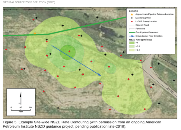
| − | + | If enough representative measurements are made across the lateral extent of the LNAPL footprint, then a site-wide estimate of NSZD can be made. Stated simply, a site-wide NSZD rate (in units of mass per time) can be estimated by multiplying a unit area NSZD rate by an estimated lateral area of the LNAPL source zone. If unit area NSZD rates have been estimated at multiple locations, each can be apportioned to a representative area and totaled to arrive at a site-wide value. Figure 5 shows an example of mapping of NSZD rates from multiple DCC measurements at a site from which the site-wide NSZD rate was estimated to be 500 gallons per year (gal/yr). | |
| − | + | ==Measuring the NSZD Thermal Expression== | |
| + | [[File: NSZD2019Fig6.png |thumb|left|450px| Figure 6a. Conceptual Model of Thermal Monitoring<ref name="ThermalNSZD2018">Thermal NSZD, 2018. Thermal NSZD: Continuous Remote Monitoring of Natural Source Zone Depletion [https://www.thermalnszd.com/index.php Thermal NSZD LLC]</ref>.]][[File:4860_NSZD_Short.mp4 |thumb|450px| Figure 6b. Thermal monitoring video.]] | ||
| + | Analogous to a compost pile which generates heat, microbial biodegradation of LNAPL is an exothermic process that results in heat being transferred to the surroundings. As seen in Figure 6a, microbial reactions include: i) methane generation in an anaerobic zone (both above and below the water table); and ii) methane oxidation in the unsaturated zone by bacteria which releases heat<ref name="ITRC2018" /><ref name="Sale2018" />. For instance, subsurface temperatures in LNAPL-impacted locations have been found to be higher than background areas, with increases ranging from 2-2.5 °C<ref name="Sweeney2014">Sweeney, R.E., Ririe, G.T., 2014. Temperature as a tool to evaluate aerobic biodegradation in hydrocarbon contaminated soil. Groundwater Monitoring & Remediation, 34(3), 41-50. [http://onlinelibrary.wiley.com/wol1/doi/10.1111/gwmr.12064/abstract doi:10.1111/gwmr.12064]</ref>, and up to 2.7 °C<ref name="Warren2015"> Warren, E., Bekins, B.A., 2015. Relating subsurface temperature changes to microbial activity at a crude oil-contaminated site. Journal of Contaminant Hydrology, 182, 183-193. [http://dx.doi.org/10.1016/j.jconhyd.2015.09.007 doi:10.1016/j.jconhyd.2015.09.007]</ref>. A video summary of Thermal Monitoring technology is presented in Figure 6b. | ||
| + | [[File:NSZD2019Fig7a.png|thumb|250px|left| Figure 7a. Thermocouples to be installed on drill rods.]][[File:NSZD2019Fig7b.png|thumb|250px| Figure 7b. Conventional Drill Rig.]] | ||
| + | [[File:NSZD2019Fig7c.png|thumb|250px| Figure 7c. Weatherproof surface equipment enclosure with solar power.]] | ||
| + | |||
| + | ===Field Installation=== | ||
| + | [[File: NSZD2019Fig8a.png |thumb|250px|left| Figure 8a. Background-corrected temperatures by depth.]] | ||
| + | [[File: NSZD2019Fig8b.png |thumb|550px|left| Figure 8b. Thermal NSZD Dashboard Graph from an LNAPL Location Indicating Fluctuating Heat Signal from Biodegradation over Time at 10 ft bgs<ref>Horst, J., Welty, N., Schnobrich, M., Sinha, P. and Kulkarni, P.R., 2017. Digital Innovation: The Next Disruptive but Transformative Remediation Frontier. Groundwater Monitoring & Remediation, 37(3), pp.19-27. [https://doi.org/10.1111/gwmr.12222 doi: 10.1111/gwmr.12222]</ref>.]] | ||
| + | For continuous, remote monitoring of temperature data, thermal monitoring stations can be installed which consist of<ref name="ThermalNSZD2018" />: | ||
| + | |||
| + | *Vertical profile of thermocouples installed by conventional drilling rigs (Figures 7a and 7b). | ||
| + | *Datalogger and wireless communication system powered by solar panel (Figure 7c). | ||
| + | *Weather-proof enclosure for monitoring electronics. | ||
| + | |||
| + | Other studies have used probes or data loggers installed in existing groundwater monitoring wells<ref name="Sweeney2014" />, or temperature data loggers housed in water-filled PVC pipe<ref name="Warren2015" />. | ||
| + | |||
| + | ===Converting Temperature to an NSZD Rate=== | ||
| + | Subsurface temperature data from a background location (i.e., clean, no underlying LNAPL impacts, away from other heat sources such as subgrade pipelines, and with similar geology, surface type and solar aspect/shading) is needed in order to subtract local temperature variations from the LNAPL-impacted location temperatures (Figures 8a and 8b). In cases where representative background temperature measurements may not be available at a site, it is possible to estimate background temperature using mathematical models<ref name="Sweeney2014" /><ref name="Hillel1977">Hillel, D., 1977. Computer simulation of soil-water dynamics: a compendium of recent work. IDRC-082e. International Development Research Centre, Ottawa, ON, CA. [//www.enviro.wiki/images/8/8a/Hillel1977.pdf report.pdf]</ref>. | ||
| + | |||
| + | Conversion of the background-corrected temperature data requires: i) evaluation of the heat flux; and ii) conversion to an NSZD rate using the heat of reaction<ref name="Sale2018" />. | ||
| + | |||
| + | Heat conduction in the subsurface can be quantified using [[wikipedia: Thermal conduction | Fourier’s Law]] for heat flux in the vertical direction as follows:<br> | ||
| + | |||
| + | ::::''qh'' = ''‐K<sub>T</sub>(ΔT/Δz)'' | ||
| + | |||
| + | where:<br> | ||
| + | |||
| + | ::''qh'' is the heat energy lost across a surface (J/m<sup>2</sup>),<br> | ||
| + | ::''K<sub>T</sub>'' is the thermal conductivity (J/m-K),<br> | ||
| + | ::''ΔT'' is the change in temperature (K), and<br> | ||
| + | ::''Δz'' is the depth interval (m) across which heat flux is calculated. <br> | ||
| + | |||
| + | The total heat flux (sum of heat flux to ground surface and heat flux downward) is converted to an NSZD rate (in gallons LNAPL degraded per acre per year) using the heat of reaction of hydrocarbon biodegradation. The approximate heat released during the complete mineralization of decane is 6,779 kJ/mol<ref name="Stockwell2015">Stockwell, E.B., 2015. Continuous NAPL loss rates using subsurface temperatures (Doctoral dissertation, Colorado State University). [//www.enviro.wiki/images/9/97/Stockwell2015.pdf report.pdf]</ref>. | ||
==Limitations and Challenges== | ==Limitations and Challenges== | ||
| − | NSZD is occurring at most petroleum release sites, however, site-specific conditions will drive the magnitude of rates. For example, the presence of a “typical” gaseous expression of NSZD ( | + | NSZD is occurring at most petroleum release sites, however, site-specific conditions will drive the magnitude of rates. For example, the presence of a “typical” gaseous expression of NSZD (Figure 1) is contingent upon the presence of LNAPL and free exchange of atmospheric oxygen with the subsurface. If the site contains predominantly impervious ground cover, then NSZD processes will deviate from that described herein, and procedures to measure it must be adapted accordingly. Many other site conditions such as low permeability soil layers, perching water or wet vadose zones, shallow water tables, and cold climates can also affect NSZD processes and must also be taken into account during the design of any NSZD monitoring plan. |
| + | |||
| + | NSZD rates measured using the methods described above quantify total hydrocarbon mass loss and do not speciate loss or degradation rates of individual chemicals such as benzene or naphthalene from soil or LNAPL phases. Therefore, the use of NSZD data for assessment of remedial timeframe, if based on time to achieve chemical-specific cleanup criteria in groundwater, for example, is limited. Current research is focused on correlating NSZD rates to better established remediation metrics such as LNAPL transmissivity and chemical-specific degradation rates. For example, Ng et al. (2015)<ref name="Ng et al 2015" /> developed a mass balance model that provides some insights on the contributions of various hydrocarbon constituent classes to the overall NSZD rate at a crude oil research site. | ||
| − | + | Thermal monitoring requires background correction, similar to methods that measure vadose zone gas transport. Proper placement of temperature transducers in LNAPL-impacted as well as background locations is necessary in order to avoid errors in interpretation of the temperature data. Background thermal monitors should be located in areas with no LNAPL impacts, but with similar geology, surface cover type (e.g., vegetation), and solar aspect/shading. Additionally, both LNAPL-impacted and background monitors should be placed in areas without any additional sources of subsurface heat (e.g., active pipelines). | |
Lastly, NSZD rates can be variable. They can fluctuate seasonally with change in ambient temperature which may induce cold/warm temperature cycles in the subsurface and also fluctuate with changes in surrounding water use (e.g., irrigation pumping). Additionally, each method has its own unique procedure and inherent assumptions, which make its measurement results difficult to compare with others. | Lastly, NSZD rates can be variable. They can fluctuate seasonally with change in ambient temperature which may induce cold/warm temperature cycles in the subsurface and also fluctuate with changes in surrounding water use (e.g., irrigation pumping). Additionally, each method has its own unique procedure and inherent assumptions, which make its measurement results difficult to compare with others. | ||
| Line 107: | Line 148: | ||
==Summary== | ==Summary== | ||
NSZD is an important process that is occurring at most petroleum release sites. Measuring the rate of NSZD can be very helpful in implementing an effective remediation strategy at these sites. Several approaches to measuring and quantifying NSZD rates are now available. However, as with most environmental remediation techniques, it is equally important to be cognizant of and account for the limitations and challenges with the approach and its associated measurements. | NSZD is an important process that is occurring at most petroleum release sites. Measuring the rate of NSZD can be very helpful in implementing an effective remediation strategy at these sites. Several approaches to measuring and quantifying NSZD rates are now available. However, as with most environmental remediation techniques, it is equally important to be cognizant of and account for the limitations and challenges with the approach and its associated measurements. | ||
| − | + | <br clear="left"> | |
==References== | ==References== | ||
| − | <references/> | + | <references /> |
==See Also== | ==See Also== | ||
| − | *[https://www.coursera.org/learn/natural-attenuation-of-groundwater-contaminants/lecture/zeSP8/natural-source-zone-depletion-nszd | + | |
| + | *[https://www.coursera.org/learn/natural-attenuation-of-groundwater-contaminants/lecture/zeSP8/natural-source-zone-depletion-nszd Online Lecture Course - Natural Source Zone Depletion] | ||
Latest revision as of 20:46, 27 April 2022
Natural source zone depletion (NSZD) is a term used to describe the collective, naturally occurring processes of dissolution, volatilization, and biodegradation that result in mass losses of light non-aqueous phase liquid (LNAPL) petroleum hydrocarbon constituents from the subsurface. NSZD is coming to the forefront of decision making at petroleum hydrocarbon remediation sites because much higher source attenuation rates are now being measured compared to previous rates based on incomplete conceptual models[1][2][3]. NSZD processes occur at most petroleum release sites and quantifying NSZD rates is an important part of an overall site remediation strategy.
Contents
Related Article(s):
Contributor(s): Tom Palaia, Jeff Fitzgibbons and Poonam Kulkarni
Key Resource(s):
- Technical Measurement Guidance for LNAPL Natural Source Zone Depletion
- Quantification of Vapor Phase-Related NSZD Processes[4]
- Evaluating Natural Source Zone Depletion at Sites with LNAPL. LNAPL-1. Washington, D.C.: Interstate Technology & Regulatory Council, LNAPLs Team.[5]
Introduction
After a release into the environment, petroleum hydrocarbon constituents in LNAPL undergo various different degradation processes including dissolution, volatilization, and biodegradation[6][7][8][9]. Natural Source Zone Depletion (NSZD) is a term used to describe these collective processes that result in mass losses of LNAPL petroleum hydrocarbon constituents from the subsurface. NSZD processes occur naturally within LNAPL-impacted zones in the subsurface. These processes physically degrade the LNAPL by mass transfer of chemical components to the aqueous and gaseous phases where they are biologically broken down via anaerobic and aerobic biodegradation.
Traditional methods of NSZD monitoring have focused on the groundwater transport of the solubilized LNAPL constituents and aqueous phase biodegradation that occurs through various terminal electron acceptor processes. Aerobic respiration, denitrification, sulfate reduction, iron and manganese reduction, and methanogenesis each support hydrocarbon degradation as the supply of each electron acceptor (e.g., dissolved oxygen, nitrate, sulfate), oxidation-reduction state, and the microbiological conditions allow. These processes manifest themselves as decreases in dissolved electron acceptor concentrations and production of soluble byproducts such as ferrous iron, dissolved methane (CH4), and carbon dioxide (CO2). Through stoichiometric conversion of the mass of electron acceptor loss and byproduct formation, the soluble or aqueous contribution to NSZD can be estimated[10][11][8].
Understanding of the gaseous expression of NSZD processes has recently improved via emerging research[12][9][13][2]. A large advance occurred with respect to the measurement of the significant amount of gases that can be produced because of anaerobic petroleum hydrocarbon biodegradation processes, predominantly methanogenesis[12]. Within the highly reduced saturated zone and overlying capillary fringe, methanogenesis occurs and generates CH4 and CO2. Because of the relatively low solubility of CH4, it is subsequently transported up to the vadose zone along with smaller amounts of CO2 and volatile organic compounds (VOCs). Within the vadose zone, LNAPL, CH4, and volatile hydrocarbons are anaerobically and aerobically biodegraded removing CH4 and oxygen (O2) from the soil gas and adding CO2. The biological oxidation of methane in the vadose zone is an exothermic process which releases heat to the surroundings[14][15]. We can conceptualize these vapor transport-related NSZD processes that are occurring at petroleum release sites as shown in Figure 1. In response to this improved understanding of NSZD, new monitoring methods have evolved to use stoichiometric conversion of the gaseous signatures left by NSZD in soil vapor or groundwater, as well as other lines of evidence such as thermal monitoring.
NSZD processes occurring within the subsurface manifest themselves as physical and chemical changes to both the aqueous and gaseous phases. The NSZD rate can be quantified by incorporating their petroleum hydrocarbon stoichiometric mass loss equivalents[5]. The methods and procedures to do this are described below.
Significance
Quantifying site-specific NSZD rates is important for various reasons. First, NSZD forms an important part of the LNAPL conceptual site model (LCSM), the written and/or illustrative representation of the physical, chemical, and biological processes that control the transport, migration, and actual/potential impacts of contamination. Within the LCSM, NSZD establishes a remediation baseline and supports interpretation of contaminant delineation and concentration trends. NSZD measurements can be used to:
- Refine the LCSM with quantification of LNAPL loss rates
- Delineate the LNAPL footprint using vadose zone indicators of biodegradation
- Support estimates of remedial timeframes
- Assess LNAPL stability through application of a mass balance of losses and measured mobile LNAPL flux[16]
Measured NSZD rates can also form the basis for remediation technology selection, design, and optimization. For example:
- Comparing LNAPL mass removal rates from NSZD to other future potential remedial actions
- Supporting a cost/benefit analysis of future remediation by evaluating the value of additional remediation compared to NSZD
- Evaluating remedial progress via periodic NSZD measurements during static, re-equilibration periods in areas of residual hydrocarbons during an active remediation program
- Using NSZD rates as an endpoint for active remediation
Throughout the remediation life cycle, measured NSZD rates can be used for a variety of decision-making purposes, ranging from technology selection to system shutdown or site closure.
Measuring the NSZD Aqueous Expression
NSZD is quantified by assuming the petroleum hydrocarbon stoichiometric equivalent of biodegradation expresses itself by changes in both the aqueous (soluble) and gaseous (vapor) phases[5]. This section covers the aqueous component. Within the saturated zone, aerobic respiration, denitrification, sulfate reduction, iron and manganese reduction, and methanogenesis each support hydrocarbon degradation and LNAPL mass loss.

For example, nitrate, iron, sulfate, and manganese reduction are some of the representative reactions for each process (Table 1). These processes manifest themselves as decreases in dissolved electron acceptor concentrations and production of soluble byproducts such as ferrous iron and dissolved CH4 and CO2. The soluble or aqueous contribution to NSZD can be estimated through stoichiometric conversion of the mass of electron acceptor loss and byproduct formation[10][8]. Because these estimates can be made using conventional groundwater sampling and analytical methods, the saturated zone component of NSZD is relatively well understood, and well-established procedures have been in place for over 20 years to monitor the NSZD process. However, conventional sampling programs often use open-system sample collection methods in which the sample is in direct contact with the atmosphere (e.g., direct fill and inverted VOA sampling methods). If the groundwater has elevated dissolved gas concentrations, some fraction of those gases may be lost to the atmosphere during sample collection.
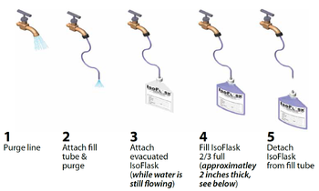
The IsoFlask methodology (Figure 2a) uses a closed system where both dissolved and effervescing gases are captured and measured in the laboratory, which may provide more accurate results of dissolved gas analysis[17]. As seen in Figure 2b, results from an NSZD site evaluation indicated higher methane and carbon dioxide dissolved gas concentrations in the LNAPL-impacted locations as compared to the clean, background location.
The aqueous contribution to NSZD, historically known as the microbiological natural attenuation rate or assimilative capacity, is typically calculated using a mass budgeting approach[8]. The mass budgeting approach estimates dissolved hydrocarbon constituent losses within the saturated zone based on changes in the aforementioned electron acceptors and byproducts across transects through the hydrocarbon plume that spans upgradient and downgradient areas. Changes in concentrations for each process are stoichiometrically converted to hydrocarbon losses using the coefficients in Table 1. Groundwater models such as BIOSCREEN combine this mass budgeting approach with an advection dispersion model[11].
Measuring the NSZD Gaseous Expression
Current NSZD practice is to evaluate the petroleum hydrocarbon stoichiometric equivalent of biodegradation in both the aqueous phase and gaseous (vapor) phase[5]. This section covers the gaseous component.
At one site, the gaseous expression of NSZD has been shown to account for >70% of the hydrocarbon biodegradation that occurs in the subsurface[18][19]. Three methods to monitor the vapor phase-related portion of NSZD are currently available and widely used. These are the gradient, passive flux trap, and dynamic closed chamber (DCC) methods elaborated on below. Method choice for a particular project is a site-specific judgment based on data quality, monitoring objectives, and site conditions.
Gradient Method
The gradient method uses O2 or CO2 concentration profiles in soil gas and select subsurface properties (e.g., effective soil gas diffusion coefficients) to estimate the flux of gases through the vadose zone using Fick’s first law[20]. The change in concentration of these gases with depth within un-impacted soil above the petroleum hydrocarbons is used as a basis for estimating the flux:
where is the effective diffusion coefficient of the gas of interest in the vadose zone soils, and
is the vertical concentration gradient of the gas being used to estimate NSZD rates. The gas flux is then stoichiometrically converted to an NSZD rate. This gradient method was the first published method to estimate NSZD[9].
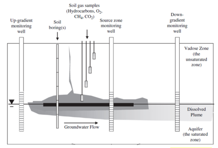
A typical gradient method NSZD monitoring setup primarily includes a nested set of soil vapor probes installed above the LNAPL-impacted soils (Figure 2c). Soil gas samples are collected from the probes using industry-standard procedures and analyzed using a field landfill gas meter (e.g., LANDTEC GEM2000).
Two key elements to implementing the gradient method include selection of the depth intervals for calculating dC/dz and estimation of Dveff. The gradient can be estimated in a linear manner, using two points, and include the ground surface and atmospheric conditions as the upper control point. The lower control point is ideally situated immediately above the hydrocarbon oxidation zone, where oxygen is depleted and methane is absent. While literature values of Dveff could be used in a screening application of the gradient method, it is best to either empirically estimate the parameter using Millington and Quirk (1961)[21] or measure it directly[22].
Passive Flux Trap

A passive flux trap is a flow-through, static chamber fitted with a chemical trap that has historically been used to measure soil-surface CO2 efflux[23]. The passive flux trap method was recently adapted for NSZD monitoring[2] and subsequently commercialized and further refined by E-Flux, LLC in Fort Collins, Colorado. The E-Flux CO2 trap employs the use of a dual-sorbent design to collect CO2 leaving the subsurface (Figure 3a). Although other configurations are possible, the trap is typcally installed in the shallow ground surface (i.e., 1–3 inches deep) and left in place for a 1–2 week timeframe. Over this time, CO2 derived from LNAPL degradation (i.e., fossil fuel-derived CO2) migrating upward from the subsurface to the atmosphere is collected inside the receiver pipe by a bottom caustic sorbent element. An upper sorbent element captures atmospheric CO2 (i.e., modern CO2) to avoid cross-contamination of the lower sorbent element, which is solely used for the NSZD estimate. The trap is deployed for a period of time that does not allow for either the top or bottom elements to become saturated with CO2. After the deployment period, the trap is retrieved and shipped to a laboratory for analysis of CO2. The CO2 efflux is estimated by dividing the trip blank-corrected mass of CO2 sorbed on the lower element by the deployment duration and the cross sectional area of the received pipe. Finally, a 14C correction is employed to separate the flux of modern CO2 flux (such as from decay of vegetation) from the “ancient” CO2 flux (from the biodegradation of petroleum products). For a more detailed explanation see the video “How Carbon Traps Work” (Figure 3b).
Dynamic Closed Chamber (DCC) Method
A DCC system is an active, specially adapted, direct measurement approach to estimate soil gas efflux at the ground surface. It pumps a small, closed loop circulation of air between a chamber set on a soil collar shallowly embedded in the ground surface and an external non-destructive gas analyzer that monitors the increase in CO2 concentration. To minimize errors associated with pressure differential inside and outside of the chamber, it is fitted with an engineered vent. DCC has been demonstrated to be a consistent efflux measurement method and used as reference for comparison to others[24]. The DCC has been used primarily for ecological carbon monitoring purposes and was recently adapted for NSZD monitoring[13]. Figure 4 shows an example DCC system, the LI-COR® 8100A automated soil flux system (LI-COR® BioSciences, Inc., Lincoln, Nebraska), and its typical setup for NSZD monitoring.
Using an internal pump, the DCC system circulates vapor that has accumulated within the chamber through a closed loop. Through continuous circulation and in-line measurement of the CO2 concentration by the non-destructive infrared gas analyzer (IRGA), the temporal increase in CO2 is recorded. The CO2 efflux is estimated using a curve fitting routine on the time series CO2 concentration data and dividing the results by the cross sectional area of the soil collar. The DCC collects rapid CO2 efflux measurements over a period of ~ 2 minutes. A series of multiple measurements are typically recorded during each field event. A long-term DCC system is also commercially available for automated, repeated measurement programs[25][26].
Gaseous Flux Background Correction
The gaseous expression of NSZD is complicated by concurrent, non-petroleum related processes that also consume O2 and create CO2[27]. These “background” processes include contributions from plant roots and microbes present in surficial and deeper soils containing natural organic matter. Therefore, correction is needed to subtract these effects prior to using the data from the gradient method and the two CO2 efflux methods (i.e., trap and DCC) for NSZD estimates. Options to eliminate the gaseous contributions of non-petroleum related sources include:
- Install measurement locations in a nearby uncontaminated setting with similar surface and subsurface conditions. Calculation of NSZD rates using this approach involves subtracting the gaseous flux measured at the background location from the total flux at each survey location atop the LNAPL footprint.
- Use radiocarbon-14 (14C) analysis on the CO2 collected from either the soil gas probes (gradient method) or the passive flux traps. The use of 14C provides an alternative, more accurate means to isolate the NSZD-derived CO2 efflux without the need to monitor outside areas. Background corrections using 14C are well documented[28][2].
Converting Gaseous Flux to an NSZD Rate
After elimination of gaseous effects due to non-petroleum processes, the corrected flux results can then be used to estimate a NSZD rate. A NSZD rate is typically expressed as a hydrocarbon degradation rate per unit area in a unit such as grams per square meter per day (g/m2/d). Using O2 or CO2 flux input, the NSZD rate is calculated by multiplying the background corrected gas flux, typically expressed as micromoles per square meter per second (μmol/m2/s), by the molar ratio of hydrocarbon degraded in a representative mineralization reaction as shown for octane:
Stoichiometry is used to determine a mass-based NSZD rate from gaseous flux data. The mass-based unit can be converted to a volume-based unit, for example gallons per square foot per day (gal/ft2/day), using the density of the predominant hydrocarbon at the site. If enough representative measurements are made over time to account for seasonal and/or hydrogeologic variability, for example, then the NSZD rate can expressed using an annual value such as gallons per acre per year (gal/ac/yr).
If enough representative measurements are made across the lateral extent of the LNAPL footprint, then a site-wide estimate of NSZD can be made. Stated simply, a site-wide NSZD rate (in units of mass per time) can be estimated by multiplying a unit area NSZD rate by an estimated lateral area of the LNAPL source zone. If unit area NSZD rates have been estimated at multiple locations, each can be apportioned to a representative area and totaled to arrive at a site-wide value. Figure 5 shows an example of mapping of NSZD rates from multiple DCC measurements at a site from which the site-wide NSZD rate was estimated to be 500 gallons per year (gal/yr).
Measuring the NSZD Thermal Expression
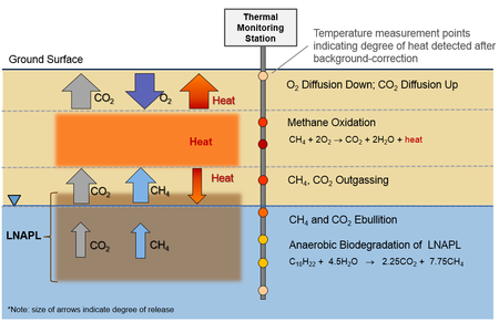
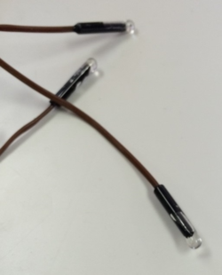
Analogous to a compost pile which generates heat, microbial biodegradation of LNAPL is an exothermic process that results in heat being transferred to the surroundings. As seen in Figure 6a, microbial reactions include: i) methane generation in an anaerobic zone (both above and below the water table); and ii) methane oxidation in the unsaturated zone by bacteria which releases heat[14][15]. For instance, subsurface temperatures in LNAPL-impacted locations have been found to be higher than background areas, with increases ranging from 2-2.5 °C[30], and up to 2.7 °C[31]. A video summary of Thermal Monitoring technology is presented in Figure 6b.
Field Installation
For continuous, remote monitoring of temperature data, thermal monitoring stations can be installed which consist of[29]:
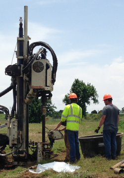
- Vertical profile of thermocouples installed by conventional drilling rigs (Figures 7a and 7b).
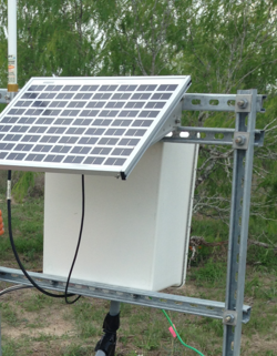
- Datalogger and wireless communication system powered by solar panel (Figure 7c).
- Weather-proof enclosure for monitoring electronics.
Other studies have used probes or data loggers installed in existing groundwater monitoring wells[30], or temperature data loggers housed in water-filled PVC pipe[31].
Converting Temperature to an NSZD Rate
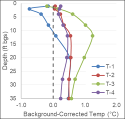
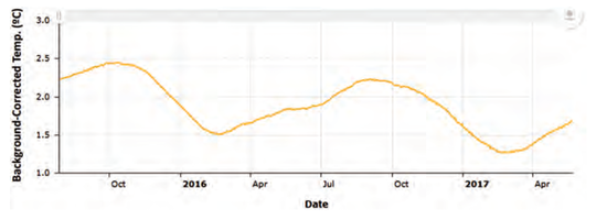
Subsurface temperature data from a background location (i.e., clean, no underlying LNAPL impacts, away from other heat sources such as subgrade pipelines, and with similar geology, surface type and solar aspect/shading) is needed in order to subtract local temperature variations from the LNAPL-impacted location temperatures (Figures 8a and 8b). In cases where representative background temperature measurements may not be available at a site, it is possible to estimate background temperature using mathematical models[30][33].
Conversion of the background-corrected temperature data requires: i) evaluation of the heat flux; and ii) conversion to an NSZD rate using the heat of reaction[15].
Heat conduction in the subsurface can be quantified using Fourier’s Law for heat flux in the vertical direction as follows:
- qh = ‐KT(ΔT/Δz)
where:
- qh is the heat energy lost across a surface (J/m2),
- KT is the thermal conductivity (J/m-K),
- ΔT is the change in temperature (K), and
- Δz is the depth interval (m) across which heat flux is calculated.
- qh is the heat energy lost across a surface (J/m2),
The total heat flux (sum of heat flux to ground surface and heat flux downward) is converted to an NSZD rate (in gallons LNAPL degraded per acre per year) using the heat of reaction of hydrocarbon biodegradation. The approximate heat released during the complete mineralization of decane is 6,779 kJ/mol[34].
Limitations and Challenges
NSZD is occurring at most petroleum release sites, however, site-specific conditions will drive the magnitude of rates. For example, the presence of a “typical” gaseous expression of NSZD (Figure 1) is contingent upon the presence of LNAPL and free exchange of atmospheric oxygen with the subsurface. If the site contains predominantly impervious ground cover, then NSZD processes will deviate from that described herein, and procedures to measure it must be adapted accordingly. Many other site conditions such as low permeability soil layers, perching water or wet vadose zones, shallow water tables, and cold climates can also affect NSZD processes and must also be taken into account during the design of any NSZD monitoring plan.
NSZD rates measured using the methods described above quantify total hydrocarbon mass loss and do not speciate loss or degradation rates of individual chemicals such as benzene or naphthalene from soil or LNAPL phases. Therefore, the use of NSZD data for assessment of remedial timeframe, if based on time to achieve chemical-specific cleanup criteria in groundwater, for example, is limited. Current research is focused on correlating NSZD rates to better established remediation metrics such as LNAPL transmissivity and chemical-specific degradation rates. For example, Ng et al. (2015)[19] developed a mass balance model that provides some insights on the contributions of various hydrocarbon constituent classes to the overall NSZD rate at a crude oil research site.
Thermal monitoring requires background correction, similar to methods that measure vadose zone gas transport. Proper placement of temperature transducers in LNAPL-impacted as well as background locations is necessary in order to avoid errors in interpretation of the temperature data. Background thermal monitors should be located in areas with no LNAPL impacts, but with similar geology, surface cover type (e.g., vegetation), and solar aspect/shading. Additionally, both LNAPL-impacted and background monitors should be placed in areas without any additional sources of subsurface heat (e.g., active pipelines).
Lastly, NSZD rates can be variable. They can fluctuate seasonally with change in ambient temperature which may induce cold/warm temperature cycles in the subsurface and also fluctuate with changes in surrounding water use (e.g., irrigation pumping). Additionally, each method has its own unique procedure and inherent assumptions, which make its measurement results difficult to compare with others.
Due to these limitations and challenges, NSZD monitoring must be performed with a firm understanding of the data objectives and use, and a sound LCSM.
Summary
NSZD is an important process that is occurring at most petroleum release sites. Measuring the rate of NSZD can be very helpful in implementing an effective remediation strategy at these sites. Several approaches to measuring and quantifying NSZD rates are now available. However, as with most environmental remediation techniques, it is equally important to be cognizant of and account for the limitations and challenges with the approach and its associated measurements.
References
- ^ Lundegard, P.D., Johnson, P.C., 2006. Source zone natural attenuation at petroleum hydrocarbon spill sites-II: application to a former oil field. Groundwater Monitoring & Remediation, 26(4), 93-106. doi:10.1111/j.1745-6592.2006.00115.x
- ^ 2.0 2.1 2.2 2.3 McCoy, K., Zimbron, J., Sale, T., Lyverse, M., 2015. Measurement of natural losses of LNAPL using CO2 traps. Groundwater, 53(4), 658-667. doi: 10.1111/gwat.12240
- ^ Palaia, T. 2016. Natural Source Zone Depletion Rate Assessment. Applied NAPL Science Review (ANSR), Volume 6, Issue 1, May.
- ^ American Petroleum Institute (API), 2017. Quantification of Vapor Phase-Related NSZD Processes, First Edition. API Publication 4784, 124 pages.
- ^ 5.0 5.1 5.2 5.3 Interstate Technology & Regulatory Council (ITRC). 2009. Evaluating Natural Source Zone Depletion at Sites with LNAPL. LNAPL-1. Washington, D.C.: Interstate Technology & Regulatory Council, LNAPLs Team. Report pdf
- ^ Kostecki, P.T., E.J. Calabrese. 1989. Petroleum Contaminated Soils, Volumes 1 through 3. Lewis Publishers, Inc., Chelsea, MI.
- ^ National Research Council, 1993. In Situ Bioremediation - When Does It Work? Committee on In Situ Bioremediation, Water Science and Technology Board, Commission on Engineering and Technical Systems, National Academy Press, Washington D.C. doi: 10.17226/2131
- ^ 8.0 8.1 8.2 8.3 National Research Council (NRC). 2000. Natural Attenuation for Groundwater Remediation. Washington, DC: The National Academies Press. doi: 10.17226/9792
- ^ 9.0 9.1 9.2 9.3 9.4 Johnson, P., Lundegard, P., Liu, Z., 2006. Source Zone Natural Attenuation at Petroleum Hydrocarbon Spill Sites-I: Site‐Specific Assessment Approach. Groundwater Monitoring & Remediation, 26(4), 82-92. doi: 10.1111/j.1745-6592.2006.00114.x
- ^ 10.0 10.1 Wiedemeier, T.H., Wilson, J.T., Kampbell, D.H., Miller, R.N. and Hansen, J.E., 1995. Technical Protocol for Implementing Intrinsic Remediation with Long-Term Monitoring for Natural Attenuation of Fuel Contamination Dissolved in Groundwater. U.S. Air Force Center for Environmental Excellence, Technology Transfer Division, Brooks Air Force Base, San Antonio, Texas. Report pdf v1 Report pdf v2a Report pdf v2b
- ^ 11.0 11.1 Newell, C.J., Gonzales, J., McLeod, R., 1996. BIOSCREEN natural attenuation decision support system, U.S. Environmental Protection Agency. EPA/600/R-96/087. Report pdf
- ^ 12.0 12.1 Amos, R.T., Mayer, K.U., Bekins, B.A., Delin, G.N., Williams, R.L., 2005. Use of dissolved and vapor‐phase gases to investigate methanogenic degradation of petroleum hydrocarbon contamination in the subsurface. Water Resources Research, 41(2). doi: 10.1029/2004WR003433
- ^ 13.0 13.1 Sihota, N.J., Singurindy, O. and Mayer, K.U., 2010. CO2-efflux measurements for evaluating source zone natural attenuation rates in a petroleum hydrocarbon contaminated aquifer. Environmental Science & Technology, 45(2), 482-488. doi: 10.1021/es1032585
- ^ 14.0 14.1 ITRC, 2018. Light Non-Aqueous Phase Liquid (LNAPL) Site Management: LCSM Evolution, Decision Process, and Remedial Technologies. LNAPL-3. Washington, D.C.
- ^ 15.0 15.1 15.2 Sale, T. C., Stockwell, E. B., Newell, C. J., Kulkarni, P. R., 2018. Devices and Methods for Measuring Thermal Flux and Estimating Rate of Change of Reactive Material within a Subsurface Formation. U.S. Patent No. 10,094,719 filed 18 February 2015. Issued 9 October 2018.
- ^ Mahler, N., Sale, T., Lyverse, M., 2012. A mass balance approach to resolving LNAPL stability. Groundwater, 50(6), 861-871. doi: 10.1111/j.1745-6584.2012.00949.x
- ^ Molofsky, L.J., Richardson, S.D., Gorody, A.W., Baldassare, F., Black, J.A., McHugh, T.E. and Connor, J.A., 2016. Effect of different sampling methodologies on measured methane concentrations in groundwater samples. Groundwater, 54(5), pp.669-680. doi: 10.1111/gwat.12415
- ^ Molins, S., Mayer, K.U., Amos, R.T., Bekins, B.A., 2010. Vadose zone attenuation of organic compounds at a crude oil spill site - Interactions between biogeochemical reactions and multicomponent gas transport. Journal of Contaminant Hydrology, 112(1), 15-29. doi: 10.1016/j.jconhyd.2009.09.002
- ^ 19.0 19.1 Ng, G-H.C., Bekins, B.A., Cozzarelli, I.M., Baedecker, M.J., Bennett, P.C., Amos, R.T., Herkelrath, W.N., 2015. Reactive transport modeling of geochemical controls on secondary water quality impacts at a crude oil spill site near Bemidji, MN. Water Resources Research, (51) pp 4156–4183. doi:10.1002/2015WR016964report.pdf
- ^ Fick, A. 1855. On liquid diffusion, Poggendorffs Annalen. 94, 59. Reprinted in Journal of Membrane Science, 1995, vol. 100, pgs. 33–38.
- ^ Millington, R.J., Quirk, J.M., 1961. Permeability of porous solids. Transaction of the Faraday Society 57, 1200–1207.
- ^ Johnson, P.C., C. Bruce, R.L. Johnson, Kemblowski, M.W., 1998. In situ measurement of effective vapor-phase porous medium diffusion coefficients. Environmental Science & Technology, 32(21), 3405–3409. doi: 10.1021/es980186q
- ^ Humfeld, H. 1930. A Method for Measuring Carbon Dioxide Evolution from Soil. Soil Science, Vol. 30(1), pp: 1-12.
- ^ Norman, J.M., Kucharik, C.J., Gower, S.T., Baldocchi, D.D., Crill, P.M., Rayment, M., Savage, K., Strieglfi, R.G., 1997. A comparison of six methods for measuring soil-surface carbon dioxide fluxes. Journal of Geophysical Research, 102(D24), 28771–28777. doi: 10.1029/97JD01440
- ^ Sihota, N.J., Trost, J.J., Bekins, B.A., Berg, A., Delin, G.N., Mason, B., Warren, E., Mayer, K.U., 2016. Seasonal Variability in Vadose Zone Biodegradation at a Crude Oil Pipeline Rupture Site. Vadose Zone Journal,15(5). doi:10.2136/vzj2015.09.0125
- ^ LI-COR Chambers. 2016. Accessed by https://www.licor.com/env/products/soil_flux/chambers.html. October 2016. Report pdf
- ^ Rochette, P., Hutchinson, G.L., 2005. Measurement of soil respiration in situ: chamber techniques. Publications from USDA-ARS / UNL Faculty. Paper 1379. Report pdf
- ^ Sihota, N.J., Mayer, K.U., 2012. Characterizing vadose zone hydrocarbon biodegradation using carbon dioxide effluxes, isotopes, and reactive transport modeling. Vadose Zone Journal, 11(4). doi:10.2136/vzj2011.0204
- ^ 29.0 29.1 Thermal NSZD, 2018. Thermal NSZD: Continuous Remote Monitoring of Natural Source Zone Depletion Thermal NSZD LLC
- ^ 30.0 30.1 30.2 Sweeney, R.E., Ririe, G.T., 2014. Temperature as a tool to evaluate aerobic biodegradation in hydrocarbon contaminated soil. Groundwater Monitoring & Remediation, 34(3), 41-50. doi:10.1111/gwmr.12064
- ^ 31.0 31.1 Warren, E., Bekins, B.A., 2015. Relating subsurface temperature changes to microbial activity at a crude oil-contaminated site. Journal of Contaminant Hydrology, 182, 183-193. doi:10.1016/j.jconhyd.2015.09.007
- ^ Horst, J., Welty, N., Schnobrich, M., Sinha, P. and Kulkarni, P.R., 2017. Digital Innovation: The Next Disruptive but Transformative Remediation Frontier. Groundwater Monitoring & Remediation, 37(3), pp.19-27. doi: 10.1111/gwmr.12222
- ^ Hillel, D., 1977. Computer simulation of soil-water dynamics: a compendium of recent work. IDRC-082e. International Development Research Centre, Ottawa, ON, CA. report.pdf
- ^ Stockwell, E.B., 2015. Continuous NAPL loss rates using subsurface temperatures (Doctoral dissertation, Colorado State University). report.pdf
