|
|
| Line 1: |
Line 1: |
| − | A Conceptual Site Model (CSM) is a collection of information about a contaminated site that integrates the available evidence regarding its hydrogeologic setting, contaminant sources, exposure pathways, potential receptors, and site history. A CSM for a [[Wikipedia: Light non-aqueous phase liquid | Light Non-Aqueous Phase Liquid (LNAPL)]] site focuses on several key concepts: the stage in the LNAPL site life cycle, LNAPL distribution in the subsurface and the resulting mobility of the LNAPL, LNAPL as a source of dissolved and vapor plumes, and the attenuation of LNAPL sources over time.
| + | ==Estimating PCE/TCE Abiotic First-Order Reductive Dechlorination Rate Constants in Clayey Soils Under Anoxic Conditions== |
| | + | The U.S. Department of Defense (DoD) faces many challenges in restoring aquifers at contaminated sites, often due to back-diffusion of tetrachloroethene (PCE) and trichloroethene (TCE) from low-permeability clay zones. The uptake, storage, and subsequent long-term release of these dissolved contaminants from clays are key processes in understanding the longevity, intensity, and risks associated with many persistent chlorinated ethene groundwater plumes. Although naturally occurring abiotic and biotic dechlorination processes in clays may reduce stored contaminant mass and significantly aid natural attenuation, no standardized field method currently exists to verify or quantify these reactions. It is critical to remediation design efforts to demonstrate and validate a cost-effective in situ approach for assessing these dechlorination processes using first-order rate constants. An approach was developed and applied across eight DoD sites to support Remedial Project Managers (RPMs) and regulators in evaluating natural attenuation potential in clay-rich environments. |
| | <div style="float:right;margin:0 0 2em 2em;">__TOC__</div> | | <div style="float:right;margin:0 0 2em 2em;">__TOC__</div> |
| | | | |
| − | '''Related Article(s)''' | + | '''Related Article(s):''' |
| − | * [[LNAPL Remediation Technologies]]
| |
| − | * [[NAPL Mobility]]
| |
| − | * [[Natural Source Zone Depletion (NSZD)]]
| |
| − | * [[Natural Attenuation in Source Zone and Groundwater Plume - Bemidji Crude Oil Spill]]
| |
| − | * [[Monitored Natural Attenuation (MNA)]]
| |
| − | * [[Biodegradation - Hydrocarbons]]
| |
| | | | |
| − | '''CONTRIBUTOR(S):''' [[Dr. Charles Newell, P.E. | Charles Newell]]
| + | *[[Monitored Natural Attenuation (MNA)]] |
| | + | *[[Monitored Natural Attenuation (MNA) of Chlorinated Solvents]] |
| | + | *[[Monitored Natural Attenuation - Transitioning from Active Remedies]] |
| | + | *[[Matrix Diffusion]] |
| | + | *[[REMChlor - MD]] |
| | | | |
| − | '''Key Resource(s):''' | + | '''Contributors:''' Dani Tran, Dr. Charles Schaefer, Dr. Charles Werth |
| − | * LNAPL Site Management: LCSM Evolution, Decision Process, and Remedial Technologies. LNAPL-3. ITRC.<ref name="LNAPL-3">Interstate Technology and Regulatory Council (ITRC), 2018. LNAPL Site Management: LCSM Evolution, Decision Process, and Remedial Technologies. LNAPL-3. ITRC, LNAPL Update Team, Washington, DC. [https://lnapl-3.itrcweb.org LNAPL-3 Website]</ref>
| |
| | | | |
| − | * Managing Risk at LNAPL Sites - Frequently Asked Questions, 2nd Edition. API.<ref name="Sale2018"> Sale, T., Hopkins, H., and Kirkman, A., 2018. Managing Risk at LNAPL Sites - Frequently Asked Questions, 2nd Edition. American Petroleum Institute (API), Washington, DC. 72 pages. [https://www.api.org/oil-and-natural-gas/environment/clean-water/ground-water/lnapl/lnapl-faqs Free download from API.] [https://www.enviro.wiki/index.php?title=File:Sale-2018_LNAPL_FAQs_2nd_ed.pdf Report.pdf]</ref> | + | '''Key Resource:''' |
| | + | *Schaefer, C.E, Tran, D., Nguyen, D., Latta, D.E., Werth, C.J., 2025. Evaluating Mineral and In Situ Indicators of Abiotic Dechlorination in Clayey Soils<ref name="SchaeferEtAl2025"/> |
| | | | |
| − | ==Life Cycle of LNAPL Sites== | + | ==Introduction== |
| − | [[File:Newell1w2Fig1.png |thumb|left|250px| Figure 1. Early, Middle, and Late Stage LNAPL releases<ref name= "Sale2018"/>. The key distinctions are the presence of continuous LNAPL that can be mobile and the amount of time that has elapsed for NSZD to remove LNAPL.]]
| + | Cost-effective methods are needed to verify the occurrence of natural dechlorination processes and quantify their dechlorination rates in clays under ambient in situ conditions in order to reliably predict their long-term influence on plume longevity and mass discharge. However, accurately determining these rates is challenging due to slow reaction kinetics, the transient nature of transformation products, and the interplay of biotic and abiotic mechanisms within the clay matrix or at clay-sand interfaces. Tools capable of quantifying these reactions and assessing their role in mitigating plume persistence would be a significant aid for long-term site management. |
| − | A Conceptual Site Model (CSM) is a collection of information about a contaminated site that integrates the available evidence regarding its hydrogeologic setting, contaminant sources, exposure pathways, potential receptors, and site history (see ASTM E1689-95(2014)<ref name="ASTM2014a"> ASTM, 2014. Standard Guide for Developing Conceptual Site Models for Contaminated Sites. ASTM E1689-95(2014), ASTM International, West Conshohocken, PA. [https://doi.org/10.1520/E1689-95R14 DOI: 10.1520/E1689-95R14] http://www.astm.org/cgi-bin/resolver.cgi?E1689</ref> and ASTM E2531-06(2014)<ref name="ASTM2014b"> ASTM, 2014. Standard Guide for Development of Conceptual Site Models and Remediation Strategies for Light Nonaqueous-Phase Liquids Released to the Subsurface. ASTM E2531-06(2014), ASTM International, West Conshohocken, PA. [https://doi.org/10.1520/E2531-06R14 DOI: 10.1520/E2531-06R14] http://www.astm.org/cgi-bin/resolver.cgi?E2531</ref>). When developing a CSM for an LNAPL site, it is important to understand that LNAPL releases evolve and change from what are referred to as Early Stage sites to Middle Stage and then to Late Stage sites<ref name="Sale2018"/> (Figure 1).
| |
| | | | |
| − | An Early Stage site is characterized by the presence of a continuous LNAPL zone where a thick layer of LNAPL accumulation (also known as free product) is observed in monitoring wells. The continuous LNAPL zone (or LNAPL body) may be mobile at Early Stage sites, migrating into previously non-impacted areas. Removal of significant LNAPL mass by active pumping may be feasible at these sites. Early Stage sites are now relatively rare in the United States due to stringent environmental regulations enacted in the 1980s which emphasized preventing releases.
| + | For reductive abiotic dechlorination under anoxic conditions, a 1% hydrochloric acid (HCl) extraction of a sample of native clay coupled with X-ray diffraction (XRD) data can be used as a screening level tool to estimate reductive dechlorination rate constants. These rate constants can be inserted into fate and transport models such as [[REMChlor - MD]]<ref>Falta, R., and Wang, W., 2017. A semi-analytical method for simulating matrix diffusion in numerical transport models. Journal of Contaminant Hydrology, 197, pp. 39-49. [https://doi.org/10.1016/j.jconhyd.2016.12.007 doi: 10.1016/j.jconhyd.2016.12.007] [[Media: FaltaWang2017.pdf | Open Access Manuscript]]</ref><ref>Kulkarni, P.R., Adamson, D.T., Popovic, J., Newell, C.J., 2022. Modeling a well-charactized perfluorooctane sulfate (PFOS) source and plume using the REMChlor-MD model to account for matrix diffusion. Journal of Contaminant Hydrology, 247, Article 103986. [https://doi.org/10.1016/j.jconhyd.2022.103986 doi: 10.1016/j.jconhyd.2022.103986] [[Media: KulkarniEtAl2022.pdf | Open Access Manuscript]]</ref> to quantify abiotic dechlorination impacts within clay aquitards on chlorinated solvent plumes. Thus, determination of the abiotic reductive dechlorination rate constant for a particular clayey soil can be readily utilized to provide a more accurate assessment of aquifer cleanup timeframes for groundwater plumes that are being sustained by contaminant back-diffusion. |
| − | [[File:Newell1w2Fig2a.png |thumb|500px| Figure 2a. Time lapse conceptualization of the formation of an LNAPL body<ref name="ITRC2019"> Interstate Technology and Regulatory Council (ITRC), 2019. LNAPL Training: Connecting the Science to Managing Sites. Part 1: Understanding LNAPL Behavior in the Subsurface. ITRC, Washington, DC. [[Media: ITRC2019_LNAPLtrainingPart1.pdf | Slides.pdf]]</ref>.]] | |
| − | [[File:Newell1w2Fig2b.png |thumb|500px| Figure 2b. Sand tank experiment of an LNAPL release<ref name="ITRC2019"/>.]]
| |
| | | | |
| − | Many sites in the U.S. are now considered to be in the Middle Stage, where the LNAPL thickness in wells has been largely depleted by natural spreading of the LNAPL body, [[Natural Source Zone Depletion (NSZD)]], smearing of the water table, and/or active remediation, and where the LNAPL bodies are stable or shrinking<ref name="LNAPL-3"/><ref name="Sale2018"/> (Figure 1). Active pumping characteristically only recovers LNAPL at relatively low rates of under 100 gallons per acre per year at Middle Stage sites, but NSZD rates may be much higher, on the order of 100s to 1,000s of gallons per acre per year. Middle Stage dissolved phase plumes, typically comprised of monoaromatics such as benzene, toluene, ethyl benzene, and xylenes, are stable or shrinking over time.
| + | ==Recommended Approach== |
| | + | [[File: TranFig1.png | thumb | 500 px | Figure 1: First-order rate constants for abiotic reductive dechlorination of TCE under anaerobic conditions. Circles are data from Schaefer ''et al.'', 2021<ref>Schaefer, C.E., Ho, P., Berns, E., Werth, C., 2021. Abiotic dechlorination in the presence of ferrous minerals. Journal of Contaminant Hydrology, 241, 103839. [https://doi.org/10.1016/j.jconhyd.2021.103839 doi: 10.1016/j.jconhyd.2021.103839] [[Media: SchaeferEtAl2021.pdf | Open Access Manuscript]]</ref>, filled squares from Schaefer ''et al.'', 2018<ref name="SchaeferEtAl2018"/>, and Schaefer ''et al.'', 2017<ref>Schaefer, C.E., Ho., Gurr, C., Berns, E., Werth, C., 2017. Abiotic dechlorination of chlorinated ethenes in natural clayey soils: impacts of mineralogy and temperature. Journal of Contaminant Hydrology, 206, pp. 10-17. [https://doi.org/10.1016/j.jconhyd.2017.09.007 doi: 10.1016/j.jconhyd.2017.09.007] [[Media: SchaeferEtAl2017.pdf | Open Access Manuscript]]</ref>, and open squares from Schaefer ''et al.'', 2025<ref name="SchaeferEtAl2025"/>. ]] |
| | + | [[File: TranFig2.png | thumb | 600 px | Figure 2: Flowchart diagram of field screening procedures]] |
| | + | The recommended approach builds upon the methodology and findings of a recent study<ref name="SchaeferEtAl2025">Schaefer, C.E., Tran, D., Nguyen, D., Latta, D.E., Werth, C.J., 2025. Evaluating Mineral and In Situ Indicators of Abiotic Dechlorination in Clayey Soils. Groundwater Monitoring and Remediation, 45(2), pp. 31-39. [https://doi.org/10.1111/gwmr.12709 doi: 10.1111/gwmr.12709]</ref>, emphasizing field-based and analytical techniques to quantify abiotic first-order reductive dechlorination rate constants for PCE and TCE in clayey soils under anoxic conditions. Key components of this evaluation are listed below: |
| | + | #<u>Zone Identification:</u> The focus of the investigation should be to delineate clayey zones adjacent to hydraulically conductive zones. |
| | + | #<u>Ferrous Mineral Quantification:</u> Assess ferrous mineral context in clay via 1% HCl extraction at ambient temperature over a 10-minute interval. |
| | + | #<u>Mineralogical Characterization:</u> Conduct XRD analysis with the specific intent of identifying the presence of pyrite and biotite. |
| | + | #<u>Reduced Gas Analysis:</u> Measurement of reduced gases such as acetylene, ethene, and ethane concentrations in clay samples. Gas-tight sampling devices (e.g., En Core® soil samplers by En Novative Technologies, Inc.) should be used to ensure sample integrity during collection and transport. |
| | | | |
| − | Late Stage sites only have a sparse distribution of residual (trapped) LNAPL due to long-term NSZD and any active remediation that has been performed at the site. The potential risks to receptors are typically low at Late Stage sites due to relatively low concentrations of LNAPL constituents in the dissolved phase and/or vapor plumes.
| + | Clay samples should be collected within a few centimeters of the high-permeability interface, with optional additional sampling further inward. For mineralogical analysis, a defined interval may be collected and subsequently subsampled. To preserve sample integrity, exposure to air should be minimized during collection, transport, and handling. Homogenization should occur within an anaerobic chamber, and if subsamples are required for external analysis, they must be shipped in gas-tight, anaerobic containers. |
| | | | |
| − | ==LNAPL Body Formation==
| + | Estimation of the abiotic reductive first-order rate constant for PCE and TCE is based on the “reactive” ferrous content in the clay. Reactive ferrous content (Fe(II)<sub>r</sub>) is estimated as shown in Equation 1: |
| − | LNAPLs released from tanks, pits, pipelines, or other sources will percolate downwards under the influence of gravity through permeable pathways in the unsaturated zone (e.g., soil pore space, fractures, and macropores) depending on the volume and pressure head of the LNAPL release, until encountering an impermeable layer or the water table, causing the LNAPL body to spread laterally. The Interstate Technology and Regulatory Council (ITRC)<ref name="LNAPL-3"/> describes this downward movement toward the water table this way:
| |
| | | | |
| − | <blockquote>''During the downward movement of LNAPL through the soil, the presence of confining layers, subsurface heterogeneities, or other preferential pathways may result in irregular and complex lateral spreading and/or perching of LNAPL before the water table is encountered. Once at the water table, the LNAPL will spread laterally in a radial fashion as well as penetrate vertically downward into the saturated zone, displacing water to some depth proportional to the driving force of the vertical LNAPL column (or LNAPL head). The vertical penetration of LNAPL into the saturated zone will continue to occur as long as the downward force produced by the LNAPL head or pressure from the LNAPL release exceeds the counteracting forces produced by the resistance of the soil matrix and the buoyancy resulting from the density difference between LNAPL and groundwater.''<ref name="LNAPL-3"/></blockquote> | + | ::'''Equation 1:''' <big>''Fe(II)<sub><small>r</small></sub> = DA + XRD<sub><small>pyr</small></sub> - XRD<sub><small>biotite</small></sub>''</big> |
| | | | |
| − | While the release at the surface is still active, the LNAPL body can expand until the LNAPL addition rate is equal to the NSZD depletion rate. However, once the release at the surface is stopped, the expansion will stop relatively quickly, and the LNAPL body will stabilize. Figure 2a shows a conceptual depiction of this release scenario and Figure 2b shows a sand tank experiment of an LNAPL release. Because of the buoyancy effects, LNAPL releases that reach the water table will form LNAPL bodies that “like icebergs, are partially above and below the water table”.<ref name="Sale2018"/>
| + | where ''DA'' is the ferrous content from the dilute acid (1% HCl) extraction, ''XRD<sub><small>pyr</small></sub>'' is the pyrite content from XRD analysis, and ''XRD<sub><small>biotite</small></sub>'' is the biotite content from XRD analysis<ref name="SchaeferEtAl2025"/>. |
| | | | |
| − | ==Key Implications of the LNAPL Conceptual Site Model==
| + | Abiotic dechlorination is unlikely to contribute to mitigating contaminant back-diffusion when reactive ferrous iron (Fe(II)<sub><small>r</small></sub>) concentrations are below 100 mg/kg (Figure 1). For Fe(II)<sub><small>r</small></sub> above 100 mg/kg, the first-order rate constant for PCE and TCE reductive dechlorination can be estimated using the correlation shown in Figure 1<ref name="SchaeferEtAl2018">Schaefer, C.E., Ho, P., Berns, E., Werth, C., 2018. Mechanisms for abiotic dechlorination of trichloroethene by ferrous minerals under oxic and anoxic conditions in natural sediments. Environmental Science and Technology, 52(23), pp.13747-13755. [https://doi.org/10.1021/acs.est.8b04108 doi: 10.1021/acs.est.8b04108]</ref><ref>Borden, R.C., Cha, K.Y., 2021. Evaluating the impact of back diffusion on groundwater cleanup time. Journal of Contaminant Hydrology, 243, Article 103889. [https://doi.org/10.1016/j.jconhyd.2021.103889 doi: 10.1016/j.jconhyd.2021] [[Media: BordenCha2021.pdf | Open Access Manuscript]]</ref>. The rate constant exhibits a strong positive correlation with the logarithm of reactive Fe(II) content (Pearson’s ''r'' = 0.82), with a slope of 4.7 × 10⁻⁸ L g⁻¹ d⁻¹ (log mg kg⁻¹)⁻¹. |
| − | The nature of multi-phase flow processes in porous media (e.g., the interaction of LNAPL, water, and air in the pore spaces of an unconsolidated aquifer) has several important implications for environmental professionals in areas including interpretation of LNAPL thickness in monitoring wells and assessment of the long-term risk associated with LNAPL source zones. A few of the key implications are described below.
| |
| | | | |
| − | ===Three States of LNAPL===
| + | Figure 2 presents a decision flowchart designed to evaluate the significance and extent of abiotic reductive dechlorination. By applying Equation 1 to the dilute acid extractable Fe(II) plus measured mineral species data from clay samples, the reactive ferrous iron content (Fe(II)<sub><small>r</small></sub>) can be quantified, enabling a streamlined assessment of the extent to which abiotic processes are contributing to the mitigation of contaminant back-diffusion. |
| − | LNAPL can be found in the subsurface in three different states:
| |
| | | | |
| − | # '''Residual LNAPL''' is trapped and immobile but can undergo composition and phase changes and generate dissolved hydrocarbon plumes in saturated zones and/or vapors in unsaturated zones. The fraction of the total pore space occupied by this discontinuous LNAPL is referred to as the residual saturation, with other phases such as water and air in the remainder of the pore space.
| + | If Fe(II)r is ≥ 100 mg/kg, a first-order dechlorination rate constant can be estimated and subsequently used within a contaminant fate and transport model. However, if acetylene is detected in the clay, even with Fe(II)r less than 100 mg/kg, then bench-scale testing using methods similar to those described in a recent study<ref name="SchaeferEtAl2025"/> is recommended, as such results would likely be inconsistent with those shown in Figure 1, suggesting some other mechanism might be involved, or that the system mineralogy might be more complex than anticipated. Even if Fe(II)r ≥ 100 mg/kg, confirmatory bench-scale testing may be conducted for additional verification and to refine estimation of the abiotic dechlorination rate constant. |
| − | # '''Mobile LNAPL''' is LNAPL at greater than the residual saturation. Mobile LNAPL can accumulate in a well and is potentially recoverable, but is not migrating (i.e., the LNAPL body is not expanding).
| |
| − | # '''Migrating LNAPL''' is LNAPL at greater than the residual concentration which is observed to expand into previously non-impacted locations over time (e.g., LNAPL appears in a monitoring well that had previously been clean).
| |
| | | | |
| − | These three LNAPL states can cause different concerns and in some cases require different remediation goals.
| + | ==Summary and Recommendations== |
| | + | The approach outlined above is intended to serve as a generalized guide for practitioners and site managers to cost-effectively determine the extent to which beneficial abiotic reductive dechlorination reactions are likely occurring in low permeability (e.g., clayey) zones. This approach may be contraindicated if co-contaminants are present. It is currently unclear whether other classes of potentially reactive chemicals, such as trinitrotoluene (TNT) or chlorinated ethanes, could interact competitively with PCE and TCE. |
| | | | |
| − | ===LNAPL “Apparent Thickness” is a Poor Metric for Risk Management===
| + | In addition, it remains unclear how other classes of compounds such as per- and polyfluoroalkyl substances (PFAS) may interact or sorb with ferrous minerals and potentially inhibit abiotic dechlorination reactions. Coupling these recommended activities with conventional site investigation tasks would provide an opportunity to perform many of the up-front screening activities with minimal additional project costs. It is important to note that the guidance proposed herein pertains to particularly low permeability media. Sites with complex or varying lithology, where the mineralogy and/or redox conditions may vary, might require evaluation of multiple samples to provide appropriate site-wide information. |
| − | [[File:Newell1w2Fig3.png |thumb|left|600px| Figure 3. Five LNAPL Thickness Scenarios for five different physical settings<ref name="Sale2018"/>.]]
| |
| − | [[File:Newell1w2Fig4.png |thumb|350px| Figure 4. Apparent LNAPL thickness versus LNAPL transmissivity, showing no correlation<ref name="Hawthorne2015">Hawthorne, J.M., 2015. Nationwide (USA) Statistical Analysis of LNAPL Transmissivity, in: R. Darlington and A.C. Barton (Chairs), Bioremediation and Sustainable Environmental Technologies—2015. Third International Symposium on Bioremediation and Sustainable Environmental Technologies (Miami, FL), page C-017, Battelle Memorial Institute, Columbus, OH. www.battelle.org/biosymp [[Media:Hawthorne2015.pdf | Abstract.pdf]]</ref>.]]
| |
| − | LNAPL thickness in monitoring wells is often referred to as the “apparent LNAPL thickness” because at first glance this LNAPL thickness might be expected to be the thickness of LNAPL that is in the formation, but in reality it is not well correlated with the thickness of the LNAPL zone in the subsurface for several reasons.
| |
| | | | |
| − | First, different physical settings can produce different LNAPL thicknesses in monitoring wells. Sale et al. (2018) show five different scenarios that produce very different responses with regard to apparent LNAPL thickness (Figure 3). Scenario A shows an LNAPL apparent thickness in the monitoring well that is at static equilibrium with LNAPL in an unconfined aquifer. Scenario B, while also an unconfined aquifer, is comprised of very fine-grained soils that cause the LNAPL thickness in the well to be much higher than in Scenario A. In Scenario C, the LNAPL has accumulated under a confined unit (likely due to an underground release of LNAPL below the confining unit), and the LNAPL has risen above the groundwater potentiometric surface, leading to a large (and misleading) LNAPL thickness in the monitoring well. Scenario D, LNAPL in a perched unit, also shows a very different response from the other scenarios. Scenario E, LNAPL in fractured system, shows that the LNAPL can penetrate below the water table, and that LNAPL thickness in a well is dependent on the pressure from accumulation of LNAPL in the fractures<ref name="Sale2018"/>.
| + | <br clear="right"/> |
| − | | |
| − | Second, apparent LNAPL thickness is affected by changes in the groundwater surface elevation (or water table). Generally, when groundwater elevations are higher than typical, the LNAPL thickness in monitoring wells will decrease or go to zero because the groundwater will redistribute any mobile LNAPL into what previously was the unsaturated zone. During lower groundwater elevation periods, much more of the LNAPL will occur as a continuous phase near the water table, leading to higher LNAPL thicknesses in wells.
| |
| − | | |
| − | Overall, LNAPL thickness measurements are useful for delineating the extent of mobile LNAPL in the saturated zone and can provide useful data for understanding the vertical distribution of LNAPL in the formation<ref name="Hawthorne2011">Hawthorne, J.M., 2011. Diagnostic Gauge Plots—Simple Yet Powerful LCSM Tools. Applied NAPL Science Review (ANSR), 1(2). [http://naplansr.com/diagnostic-gauge-plots-volume-1-issue-2-february-2011/ Website] [[Media:Hawthorne2011.pdf | Report.pdf]]</ref><ref name="Kirkman2013">Kirkman, A.J., Adamski, M., and Hawthorne, M., 2013. Identification and Assessment of Confined and Perched LNAPL Conditions. Groundwater Monitoring and Remediation, 33 (1), pp. 75–86. [https://doi.org/10.1111/j.1745-6592.2012.01412.x DOI:10.1111/j.1745-6592.2012.01412.x]</ref>. But LNAPL thickness by itself is a very poor indicator of the feasibility of LNAPL recovery<ref name="LNAPL-2">Interstate Technology and Regulatory Council (ITRC), 2009. Evaluating LNAPL Remedial Technologies for Achieving Project Goals. LNAPL-2. ITRC, LNAPLs Team, Washington, DC. www.itrcweb.org [[Media:ITRC-LNAPL-2.pdf | Report.pdf]]</ref><ref name="Hawthorne2015"/> (see [[NAPL Mobility]]) (Figure 4). Because there is little correlation between apparent LNAPL thickness and LNAPL mobility, there is also little correlation between apparent thickness and the risk to receptors from the LNAPL.
| |
| − | | |
| − | ===Complete LNAPL Remediation Is Very Challenging===
| |
| − | Sale et al. (2018) described the problems with attaining complete LNAPL remediation this way:
| |
| − | | |
| − | <blockquote>''Experience of the last few decades has taught us: 1) our best efforts often leave some LNAPL in place, and 2) the remaining LNAPL often sustains exceedances of drinking water standards in release areas for extended periods. Entrapment of LNAPLs at residual saturations is a primary factor constraining our success. Other challenges include the low solubility of LNAPL, the complexity of the subsurface geologic environment, access limitations associated with surface structures, and concentration goals that are often three to five orders of magnitude less than typical initial concentrations within LNAPL zones.''<ref name="Sale2018"/></blockquote>
| |
| − | | |
| − | In particular, the discontinuous residual LNAPL cannot be removed (or recovered) by pumping, and ''in situ'' remediation is expensive and not completely effective (see [[LNAPL Remediation Technologies]]). However, many regulatory programs require “LNAPL recovery to the extent practicable.” The lack of quantitative metrics and the lack of correlation between apparent LNAPL thicknesses and subsurface LNAPL makes this a problematic requirement in many cases and the ITRC (2018) cautions “Thickness or concentration data alone may not provide a sound basis for defining the point at which a cleanup objective is achieved.”<ref name="LNAPL-3"/> However, Sale et al. (2018) describe metrics such as LNAPL transmissivity, limited/infrequent well thicknesses, decline curve analysis, asymptotic analysis, and comparison to NSZD rates that can be used to determine when LNAPL has been removed the extent practicable<ref name="Sale2018"/>.
| |
| − | | |
| − | ===Attenuation Processes are Active and Important===
| |
| − | Both LNAPL source zones and their dissolved phase hydrocarbon plumes are attenuated by biodegradation and other attenuation process. In the source zone, this attenuation is called [[Natural Source Zone Depletion (NSZD)]] (see also [[Natural Attenuation in Source Zone and Groundwater Plume - Bemidji Crude Oil Spill]]). In the dissolved plume it is called [[Monitored Natural Attenuation (MNA)]] (see also [[Biodegradation - Hydrocarbons]]). These processes generally limit the length of dissolved phase hydrocarbon plumes to a few hundred feet<ref name="Newell1998">Newell, C.J., and Connor, J.A., 1998. Characteristics of Dissolved Hydrocarbon Plumes: Results from Four Studies, Version 1.1. American Petroleum Institute, Soil/Groundwater Technical Task Force, Washington, DC. [https://www.enviro.wiki/index.php?title=File:Newell-1998-chararacterization_of_dissolved_Pet._Hydro_Plumes.pdf Report.pdf]</ref> via processes that have been well known and understood since the mid-1990s.
| |
| − | | |
| − | However, NSZD is “by far, the biggest new idea for LNAPLs in the last decade.”<ref name="Sale2018"/> Originally, LNAPL bodies were thought to attenuate very slowly via dissolution and volatilization. In 2006, it was discovered that NSZD rates are orders of magnitude higher than originally thought, largely due to direct biodegradation of LNAPL constituents to methane and carbon dioxide by methanogenic consortiums of naturally occurring bacteria<ref name="Lundegard2006">Lundegard, P.D., and Johnson, P.C., 2006. Source Zone Natural Attenuation at Petroleum Spill Sites—II: Application to a Former Oil Field. Groundwater Monitoring and Remediation. 26(4), pp. 93-106. [ https://doi.org/10.1111/j.1745-6592.2006.00115.x DOI: 10.1111/j.1745-6592.2006.00115.x]</ref><ref name="Garg2017">Garg, S., Newell, C., Kulkarni, P., King, D., Adamson, D.T., Irianni Renno, M., and Sale, T., 2017. Overview of Natural Source Zone Depletion: Processes, Controlling Factors, and Composition Change. Groundwater Monitoring and Remediation, 37(3), pp. 62-81. [https://doi.org/10.1111/gwmr.12219 DOI: 10.1111/gwmr.12219] [[Media:Garg2017gwmr.12219.pdf | Report.pdf]]</ref>. NSZD processes play an important role in risk mitigation and the long-term stability of LNAPL bodies<ref name="Mahler2012">
| |
| − | Mahler, N., Sale, T., and Lyverse, M., 2012. A Mass Balance Approach to Resolving LNAPL Stability. Groundwater, 50(6), pp 861-871. [https://doi.org/10.1111/j.1745-6584.2012.00949.x DOI: 10.1111/j.1745-6584.2012.00949.x]</ref><ref name="LNAPL-3"/>.
| |
| − | | |
| − | ===Risk from LNAPL Source Zones Diminishes Over Time===
| |
| − | At Early Stage LNAPL sites, the expansion of the LNAPL body is a risk that needs to be addressed. Fortunately, this type of site is relatively rare. For Middle and Late Stage sites, the primary risks are associated with phase changes (dissolution of the LNAPL forming a dissolved plume and volatilization from the LNAPL or dissolved plume forming hydrocarbon vapors). As described above, MNA can often control the dissolved phase (see [[Monitored Natural Attenuation (MNA) of Fuels]]), while aerobic biodegradation in the unsaturated zone greatly reduces the vapor intrusion risk from hydrocarbon vapors (see [[Vapor Intrusion - Separation Distances from Petroleum Sources]]).
| |
| − | | |
| − | Understanding LNAPL body mobility and stability is important to understand the potential risks posed by LNAPL. The relative magnitude of LNAPL mobility can be determined by measuring the LNAPL transmissivity (see [[NAPL Mobility]]). If the transmissivity is below a threshold level (in the range of 0.1 to 0.8 ft2/day) then the LNAPL likely cannot be recovered efficiently by pumping, but above this transmissivity level recovery is feasible<ref name="LNAPL-3"/>. Michigan’s LNAPL guidance states “if the NAPL has a transmissivity greater than 0.5 ft2/day, it is likely that the NAPL can be recovered in a cost-effective and efficient manner unless a demonstration is made to show otherwise.” Kansas LNAPL guidance requires “recovery of all LNAPL with a transmissivity greater than 0.8 ft2/day that can be recovered in an efficient, cost-effective manner.”<ref name="LNAPL-3"/>. The stability of the entire LNAPL body can be evaluated using statistical tools to determine if migration of LNAPL is occurring<ref name="Hawthorne2013">Hawthorne, J.M., Stone, C.D., Helsel, D., 2013. LNAPL Body Stability Part 2: Daughter Plume Stability via Spatial Moments Analysis. Applied NAPL Science Review (ANSR), 3(5). [http://naplansr.com/lnapl-body-stability-part-2-daughter-plume-stability-via-spatial-moments-analysis-volume-3-issue-5-september-2013/ Website] [[Media:Hawthorne2013.pdf | Report.pdf]]</ref>.
| |
| − | | |
| − | ==Overview of Modern LNAPL Conceptual Site Model==
| |
| − | [[File:Newell1w2Fig5.png |thumb|500px| Figure 5. A higher tier of LNAPL CSM is useful as LNAPL site complexity increases<ref name="LNAPL-3"/>.]]
| |
| − | The ITRC (2018) describes the typical evolution of an LCSM over the course of the remediation process which can be broken into three separate stages:
| |
| − | * An ''Initial LCSM'' focuses on identifying the LNAPL concerns, such as a risk to health or safety, any LNAPL migration, LNAPL-specific regulations, and physical or aesthetic impacts.
| |
| − | * A ''Remedy Selection LCSM'' supports remedial technology evaluation by characterizing aspects of the LNAPL and site subsurface that may impact remedial technology performance.
| |
| − | * A ''Design and Performance LCSM'' focuses on presenting the technical information needed to establish remediation objectives, design and implement remedies or control measures, and track progress toward defined remediation endpoints.
| |
| − | | |
| − | One key question when developing an LCSM is “how much data is enough.” In general, the answer is that the existing data is sufficient for the current stage of the remediation project when it allows the stakeholders to agree on a path forward<ref name="LNAPL-3"/>. Figure 5 shows that as the level of complexity of a site increases, a higher tier of LCSM is useful to provide enough information for making decisions<ref name="LNAPL-3"/><ref name="ASTM2014a"/>. The higher tier of information could be higher data density, additional tools for a given line of evidence, or other evaluations.
| |
| − | | |
| − | ==LNAPL Concerns, Remediation Goals and Objectives==
| |
| − | Finally, the ITRC (2018) provides a methodology for identifying LNAPL concerns, verifying those concerns, selecting LNAPL remediation goals, and determining LNAPL remediation objectives. Examples of each of these concepts are provided below:
| |
| − | | |
| − | * '''Potential Concerns:''' Human or ecological risk concerns, fire or explosivity issues, LNAPL migration, LNAPL-specific regulatory concerns, other concerns such as odors or geotechnical issues.
| |
| − | * '''Verifying Concerns:''' Measure LNAPL transmissivity to determine if it is recoverable; measure vertical and horizontal separation distances between buildings and LNAPL bodies to screen for vapor intrusion concerns.
| |
| − | * '''Remediation Goals:''' Reduce mobile LNAPL saturation, abate unacceptable soil concentrations, terminate LNAPL body migration, abate unacceptable constituent concentrations in dissolved and vapor phases.
| |
| − | * '''Remediation Objectives:''' Recover LNAPL to the extent practicable based on transmissivity, reduce soil concentrations to below regulatory limits, stop LNAPL migration with a barrier, contain migrating groundwater plume (if present), reduce groundwater and vapor concentration to acceptable levels.
| |
| − | * '''Remediation Technologies:''' LNAPL Mass Recovery technologies, LNAPL phase change technologies, LNAPL Mass Control technologies, combinations of technologies.
| |
| − | | |
| − | Overall, a LNAPL Conceptual Site Model that integrates key site specific information and current technical knowledge about LNAPL sites in general is instrumental to successful site management, where LNAPL concerns drive remediation goals, goals drive remediation objectives, and the objectives form the basis for the selection of remediation technologies.
| |
| | | | |
| | ==References== | | ==References== |
| − | | + | <references /> |
| − | <references/> | |
| | | | |
| | ==See Also== | | ==See Also== |
| − |
| + | *[https://serdp-estcp.mil/projects/details/a7e3f7b5-ed82-4591-adaa-6196ff33dd60 ESTCP Project ER20-5031 – In Situ Verification and Quantification of Naturally Occurring Dechlorination Rates in Clays: Demonstrating Processes that Mitigate Back-Diffusion and Plume Persistence] |
Estimating PCE/TCE Abiotic First-Order Reductive Dechlorination Rate Constants in Clayey Soils Under Anoxic Conditions
The U.S. Department of Defense (DoD) faces many challenges in restoring aquifers at contaminated sites, often due to back-diffusion of tetrachloroethene (PCE) and trichloroethene (TCE) from low-permeability clay zones. The uptake, storage, and subsequent long-term release of these dissolved contaminants from clays are key processes in understanding the longevity, intensity, and risks associated with many persistent chlorinated ethene groundwater plumes. Although naturally occurring abiotic and biotic dechlorination processes in clays may reduce stored contaminant mass and significantly aid natural attenuation, no standardized field method currently exists to verify or quantify these reactions. It is critical to remediation design efforts to demonstrate and validate a cost-effective in situ approach for assessing these dechlorination processes using first-order rate constants. An approach was developed and applied across eight DoD sites to support Remedial Project Managers (RPMs) and regulators in evaluating natural attenuation potential in clay-rich environments.
Related Article(s):
Contributors: Dani Tran, Dr. Charles Schaefer, Dr. Charles Werth
Key Resource:
- Schaefer, C.E, Tran, D., Nguyen, D., Latta, D.E., Werth, C.J., 2025. Evaluating Mineral and In Situ Indicators of Abiotic Dechlorination in Clayey Soils[1]
Introduction
Cost-effective methods are needed to verify the occurrence of natural dechlorination processes and quantify their dechlorination rates in clays under ambient in situ conditions in order to reliably predict their long-term influence on plume longevity and mass discharge. However, accurately determining these rates is challenging due to slow reaction kinetics, the transient nature of transformation products, and the interplay of biotic and abiotic mechanisms within the clay matrix or at clay-sand interfaces. Tools capable of quantifying these reactions and assessing their role in mitigating plume persistence would be a significant aid for long-term site management.
For reductive abiotic dechlorination under anoxic conditions, a 1% hydrochloric acid (HCl) extraction of a sample of native clay coupled with X-ray diffraction (XRD) data can be used as a screening level tool to estimate reductive dechlorination rate constants. These rate constants can be inserted into fate and transport models such as REMChlor - MD[2][3] to quantify abiotic dechlorination impacts within clay aquitards on chlorinated solvent plumes. Thus, determination of the abiotic reductive dechlorination rate constant for a particular clayey soil can be readily utilized to provide a more accurate assessment of aquifer cleanup timeframes for groundwater plumes that are being sustained by contaminant back-diffusion.
Recommended Approach
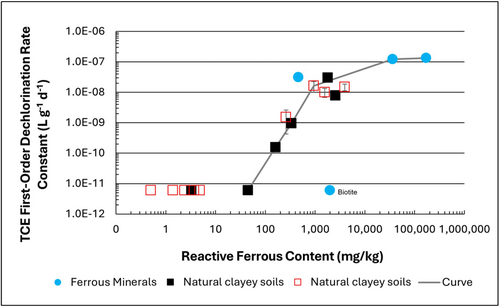
Figure 1: First-order rate constants for abiotic reductive dechlorination of TCE under anaerobic conditions. Circles are data from Schaefer
et al., 2021
[4], filled squares from Schaefer
et al., 2018
[5], and Schaefer
et al., 2017
[6], and open squares from Schaefer
et al., 2025
[1].
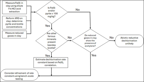
Figure 2: Flowchart diagram of field screening procedures
The recommended approach builds upon the methodology and findings of a recent study[1], emphasizing field-based and analytical techniques to quantify abiotic first-order reductive dechlorination rate constants for PCE and TCE in clayey soils under anoxic conditions. Key components of this evaluation are listed below:
- Zone Identification: The focus of the investigation should be to delineate clayey zones adjacent to hydraulically conductive zones.
- Ferrous Mineral Quantification: Assess ferrous mineral context in clay via 1% HCl extraction at ambient temperature over a 10-minute interval.
- Mineralogical Characterization: Conduct XRD analysis with the specific intent of identifying the presence of pyrite and biotite.
- Reduced Gas Analysis: Measurement of reduced gases such as acetylene, ethene, and ethane concentrations in clay samples. Gas-tight sampling devices (e.g., En Core® soil samplers by En Novative Technologies, Inc.) should be used to ensure sample integrity during collection and transport.
Clay samples should be collected within a few centimeters of the high-permeability interface, with optional additional sampling further inward. For mineralogical analysis, a defined interval may be collected and subsequently subsampled. To preserve sample integrity, exposure to air should be minimized during collection, transport, and handling. Homogenization should occur within an anaerobic chamber, and if subsamples are required for external analysis, they must be shipped in gas-tight, anaerobic containers.
Estimation of the abiotic reductive first-order rate constant for PCE and TCE is based on the “reactive” ferrous content in the clay. Reactive ferrous content (Fe(II)r) is estimated as shown in Equation 1:
- Equation 1: Fe(II)r = DA + XRDpyr - XRDbiotite
where DA is the ferrous content from the dilute acid (1% HCl) extraction, XRDpyr is the pyrite content from XRD analysis, and XRDbiotite is the biotite content from XRD analysis[1].
Abiotic dechlorination is unlikely to contribute to mitigating contaminant back-diffusion when reactive ferrous iron (Fe(II)r) concentrations are below 100 mg/kg (Figure 1). For Fe(II)r above 100 mg/kg, the first-order rate constant for PCE and TCE reductive dechlorination can be estimated using the correlation shown in Figure 1[5][7]. The rate constant exhibits a strong positive correlation with the logarithm of reactive Fe(II) content (Pearson’s r = 0.82), with a slope of 4.7 × 10⁻⁸ L g⁻¹ d⁻¹ (log mg kg⁻¹)⁻¹.
Figure 2 presents a decision flowchart designed to evaluate the significance and extent of abiotic reductive dechlorination. By applying Equation 1 to the dilute acid extractable Fe(II) plus measured mineral species data from clay samples, the reactive ferrous iron content (Fe(II)r) can be quantified, enabling a streamlined assessment of the extent to which abiotic processes are contributing to the mitigation of contaminant back-diffusion.
If Fe(II)r is ≥ 100 mg/kg, a first-order dechlorination rate constant can be estimated and subsequently used within a contaminant fate and transport model. However, if acetylene is detected in the clay, even with Fe(II)r less than 100 mg/kg, then bench-scale testing using methods similar to those described in a recent study[1] is recommended, as such results would likely be inconsistent with those shown in Figure 1, suggesting some other mechanism might be involved, or that the system mineralogy might be more complex than anticipated. Even if Fe(II)r ≥ 100 mg/kg, confirmatory bench-scale testing may be conducted for additional verification and to refine estimation of the abiotic dechlorination rate constant.
Summary and Recommendations
The approach outlined above is intended to serve as a generalized guide for practitioners and site managers to cost-effectively determine the extent to which beneficial abiotic reductive dechlorination reactions are likely occurring in low permeability (e.g., clayey) zones. This approach may be contraindicated if co-contaminants are present. It is currently unclear whether other classes of potentially reactive chemicals, such as trinitrotoluene (TNT) or chlorinated ethanes, could interact competitively with PCE and TCE.
In addition, it remains unclear how other classes of compounds such as per- and polyfluoroalkyl substances (PFAS) may interact or sorb with ferrous minerals and potentially inhibit abiotic dechlorination reactions. Coupling these recommended activities with conventional site investigation tasks would provide an opportunity to perform many of the up-front screening activities with minimal additional project costs. It is important to note that the guidance proposed herein pertains to particularly low permeability media. Sites with complex or varying lithology, where the mineralogy and/or redox conditions may vary, might require evaluation of multiple samples to provide appropriate site-wide information.
References
- ^ 1.0 1.1 1.2 1.3 1.4 Schaefer, C.E., Tran, D., Nguyen, D., Latta, D.E., Werth, C.J., 2025. Evaluating Mineral and In Situ Indicators of Abiotic Dechlorination in Clayey Soils. Groundwater Monitoring and Remediation, 45(2), pp. 31-39. doi: 10.1111/gwmr.12709
- ^ Falta, R., and Wang, W., 2017. A semi-analytical method for simulating matrix diffusion in numerical transport models. Journal of Contaminant Hydrology, 197, pp. 39-49. doi: 10.1016/j.jconhyd.2016.12.007 Open Access Manuscript
- ^ Kulkarni, P.R., Adamson, D.T., Popovic, J., Newell, C.J., 2022. Modeling a well-charactized perfluorooctane sulfate (PFOS) source and plume using the REMChlor-MD model to account for matrix diffusion. Journal of Contaminant Hydrology, 247, Article 103986. doi: 10.1016/j.jconhyd.2022.103986 Open Access Manuscript
- ^ Schaefer, C.E., Ho, P., Berns, E., Werth, C., 2021. Abiotic dechlorination in the presence of ferrous minerals. Journal of Contaminant Hydrology, 241, 103839. doi: 10.1016/j.jconhyd.2021.103839 Open Access Manuscript
- ^ 5.0 5.1 Schaefer, C.E., Ho, P., Berns, E., Werth, C., 2018. Mechanisms for abiotic dechlorination of trichloroethene by ferrous minerals under oxic and anoxic conditions in natural sediments. Environmental Science and Technology, 52(23), pp.13747-13755. doi: 10.1021/acs.est.8b04108
- ^ Schaefer, C.E., Ho., Gurr, C., Berns, E., Werth, C., 2017. Abiotic dechlorination of chlorinated ethenes in natural clayey soils: impacts of mineralogy and temperature. Journal of Contaminant Hydrology, 206, pp. 10-17. doi: 10.1016/j.jconhyd.2017.09.007 Open Access Manuscript
- ^ Borden, R.C., Cha, K.Y., 2021. Evaluating the impact of back diffusion on groundwater cleanup time. Journal of Contaminant Hydrology, 243, Article 103889. doi: 10.1016/j.jconhyd.2021 Open Access Manuscript
See Also

