Difference between revisions of "Thermal Remediation - Desorption"
m (1 revision imported) |
m (1 revision imported) |
| (10 intermediate revisions by the same user not shown) | |
(No difference)
| |
Revision as of 20:57, 4 May 2018
In situ thermal desorption (ISTD) is based on simple heating by thermal conduction in combination with fluid extraction. Elevated subsurface temperatures mobilize contaminants for extraction. ISTD is an effective and predictable solution for organic source zones, and can be combined with less aggressive methods for complete site and plume restoration (e.g., see Thermal Remediation - Combined Remedies).
Related Article(s):
- Thermal Remediation
- Thermal Remediation - Steam
- Thermal Remediation - Electrical Resistance Heating
- Thermal Remediation - Combined Remedies
CONTRIBUTOR(S): Dr. Gorm Heron
Key Resource(s):
- Removal of PCE DNAPL from Tight Clays using In Situ Thermal Desorption[1]
- Thermal Conduction Heating for In-Situ Thermal Desorption of Soils.[2]
Introduction
The principle of ISTD is to use thermal conduction to distribute heat throughout the contaminated subsurface volume, raising the temperature high enough to mobilize and extract the chemicals. ISTD treatment is commonly used at sites with significant contamination and a reason to clean up quickly. When the treatment zone is delineated well, and the ISTD system designed and implemented with care, near complete removal of the contaminants is possible.
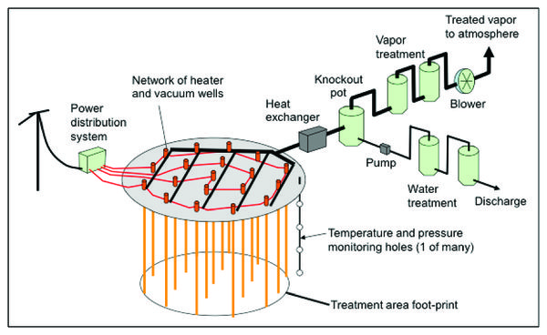
ISTD sites have a heating system, which delivers the energy to the treatment volume, and an extraction and treatment system that pulls the contaminants and vapors out of the ground and then separates and treats the vapors and fluids (Fig. 1). The soil is heated by simple thermal conduction via heated metal pipes in the ground. Typical ISTD systems utilize circuits of electrically powered heaters that are spaced systematically throughout the thermal treatment zone (TTZ) in a triangular pattern. Gas may also be used to heat the boreholes, requiring gas burners to be placed at each boring. The ISTD technology is flexible in that it allows for a wide range of desired treatment temperatures based on the contaminants at the site.
Thermal conductivity values for the entire range of known soils vary by a factor of < +/- 3, while fluid conductivity values of soils may vary by a factor of a million or more. Compared to fluid injection processes and other thermal technologies, the conductive heating process is more uniform in its vertical and horizontal sweep. Transport of the vaporized contaminants is further improved by increases in gas permeability, which results from drying of the soil close to the heaters[1]. Preferential flow paths are created even in tight silt and clay layers, allowing flow and capture of the vaporized contaminants. Thermal conduction produces more uniform heat transfer through conduction and convection in the bulk of the soil volume, resulting in high contaminant removal efficiency[1].
Temperature and pressure monitoring wells are used to document performance of the heating and treatment (Fig. 1). Target temperatures are derived based on the contaminants of concern (COCs) and treatment goals.
ISTD can be applied at low (<100°C), moderate (~100°C), and higher (>100°C) temperature levels to remediate a wide variety of contaminants, both above and below the water table. In order to heat to higher temperatures, pumping and/or vaporization must remove the naturally occurring pore and groundwater. In some instances, hydraulic barriers are used to facilitate dewatering prior to heating.
Before ISTD treatment is considered complete, soil samples are typically collected and used to show that the remedial goals are met. Then, cool-down and site demobilization activities begin. If the interim sampling reveals areas with contamination above the project's criteria, system modifications and prolonged operation are used to reach the goals.
Applications

Because ISTD is based in simple heat conduction, it can be used above and below the water table. Water is not needed for facilitating heating, so temperatures above the boiling point of water are achievable for treating semi-volatile contaminants[3]. ISTD has been used routinely to treat volatiles such as trichloroethylene (TCE) and tetrachloroethene (PCE) as well[1][4][5].
Example COCs include: Chlorinated solvents, Non-aqueous phase liquids (NAPLs), Tar, Polychlorinated biphenyls (PCBs), Pesticides, Polycyclic aromatic hydrocarbons (PAHs), Mercury, Dioxins, Fuels and heavy hydrocarbons, 1,4-Dioxane
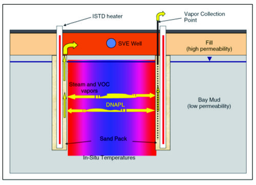
Target treatment temperatures are typically 90-100°C for volatile contaminants and between 150°C and 335°C for semi-volatile contaminants. A typical application for volatile organics above and below the water table includes heating rods that flank the area of concern (Fig. 2). For chlorinated solvents, the target temperature is typically 100°C.
ISTD is scalable and well-suited for large and deep sites, and when properly implemented it can lead to effective site closure[4]. When combined with Thermal Remediation - Steam, solutions are available for sites with substantial groundwater flow as well. ISTD has also been proven effective for removal of dense non-aqueous phase liquid (DNAPL) in fractured rock[6]. When the treatment zone is properly delineated, and the thermal system implemented well, very high treatment efficiencies are achieved.
Case Studies
ISTD has been used for sites with significant contamination and strong reasons to remediate. Examples are:
- Treatment of a 108-ft deep creosote spill at a site in northern Los Angeles, CA. The source zone was heated and treated at temperatures of 335°C. Residential remedial goals were met after removal of more than 1 million lbs or organics, and the client received a no further action letter that allowed unrestricted use of the property[3].
- Remediation of a chlorinated solvent source area in tight clays beneath a building near the San Francisco Bay. ISTD treatment took 110 days and target temperatures were 100°C. Removal of the mass and attainment of the soil standards allowed for redevelopment of the site[1].
- A source zone beneath a former dry cleaner had led to a long-dissolved plume and vapor intrusion into homes. ISTD was used to heat the source to 100°C, remove > 99.9% of the chlorinated solvents, and resulted in achievement of the remedial goals. The source treatment resulted in substantially reduced mass discharge into the dissolved plume. Five years after ISTD treatment, the client obtained permission to discontinue the pump and treat system[5].
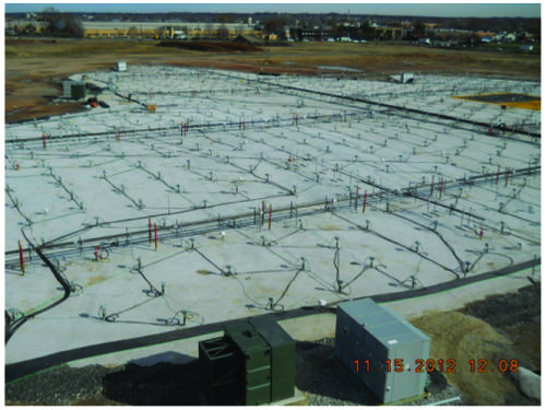
- Redevelopment of an industrial area near the Teterboro airport in New Jersey was only possible after treatment of a 3.2-acre chlorinated solvent source area. ISTD was used to heat and treat the site, reaching the boiling point of water and the soil standards. Several challenges related to the large scale were identified and overcome, resulting in successful project completion[4]. Figure 3 shows the large well field used to remove the DNAPL and meet remedial goals.
These case studies illustrate the type of sites addressed with ISTD. Common themes are (1) significant source contamination and (2) a remediation driver that makes rapid site restoration attractive.
Summary
In situ thermal desorption can be effective for treating heavily contaminated source zones to low levels. The simplicity of the heating makes ISTD a robust solution for complex sites, reducing uncertainties related to subsurface heterogeneity and properties. It can also be effective for treatment of semi-volatile organics that require temperatures above the boiling point of water, and for organic source zones in fractured rock.
References
- ^ 1.0 1.1 1.2 1.3 1.4 1.5 Heron, G., Lachance, J. and Baker, R., 2013. Removal of PCE DNAPL from tight clays using in situ thermal desorption. Groundwater Monitoring & Remediation, 33(4), 31-43. doi:10.1111/gwmr.12028
- ^ Stegemeier, G.L. and Vinegar, H.J., 2001. Thermal conduction heating for in-situ thermal desorption of soils. In Chang H. Oh (ed.), Hazardous and Radioactive Waste Treatment Technol. Handbook, CRC Press, Boca Raton, FL. Chapter, 4, pgs. 1-37. ISBN 9780849395864.
- ^ 3.0 3.1 Baker, R.S., Bierschenk, J.M., LaChance, J., Heron, G., Phelan, D., and Clock, J.A., 2010. In situ thermal treatment of MGP waste and creosote. Paper H-057, in K.A. Fields and G.B. Wickramanayake (Chairs), Remediation of Chlorinated and Recalcitrant Compounds - 2010. Seventh International Conference on Remediation of Chlorinated and Recalcitrant Compounds, Monterey, CA. Battelle Memorial Institute, Columbus, OH.
- ^ 4.0 4.1 4.2 Heron, G., Parker, K., Fournier, S., Wood, P., Angyal, G., Levesque, J. and Villecca, R., 2015. World's Largest In Situ Thermal Desorption Project: Challenges and Solutions. Groundwater Monitoring & Remediation, 35(3), 89-100. doi: 10.1111/gwmr.12115
- ^ 5.0 5.1 Heron, G., Bierschenk, J., Swift, R., Watson, R. and Kominek, M., 2016. Thermal DNAPL source zone treatment impact on a CVOC plume. Groundwater Monitoring & Remediation, 36(1), 26-37. doi: 10.1111/gwmr.12148
- ^ Heron, G., Baker, R.S., Bierschenk, J.M., and LaChance, J., 2008. Use of thermal conduction heating for the remediation of DNAPL in fractured bedrock. Paper P-003, in: Bruce M. Sass (Conference Chair), Remediation of Chlorinated and Recalcitrant Compounds. Proceedings of the Sixth International Conference on Remediation of Chlorinated and Recalcitrant Compounds, Monterey, CA. Battelle Press, Columbus, OH.

