Difference between revisions of "File:Slater Intro Fig2.jpg"
Debra Tabron (talk | contribs) (Figure 2. Example of a surface-based geophysical method. (a) Schematic diagram of an electromagnetic induction tool in operation, which comprises a transmitter (Tx) and receiver (Rx) to respectively produce a primary electromagnetic field and measure a...) |
(No difference)
|
Latest revision as of 14:52, 31 January 2017
Figure 2. Example of a surface-based geophysical method. (a) Schematic diagram of an electromagnetic induction tool in operation, which comprises a transmitter (Tx) and receiver (Rx) to respectively produce a primary electromagnetic field and measure a secondary electromagnetic field affected by the Earth’s electrical structure. (b) Photograph showing a multi-frequency electromagnetic induction tool in operation at a remediation site in Brandywine, MD.
File history
Click on a date/time to view the file as it appeared at that time.
| Date/Time | Thumbnail | Dimensions | User | Comment | |
|---|---|---|---|---|---|
| current | 14:52, 31 January 2017 | 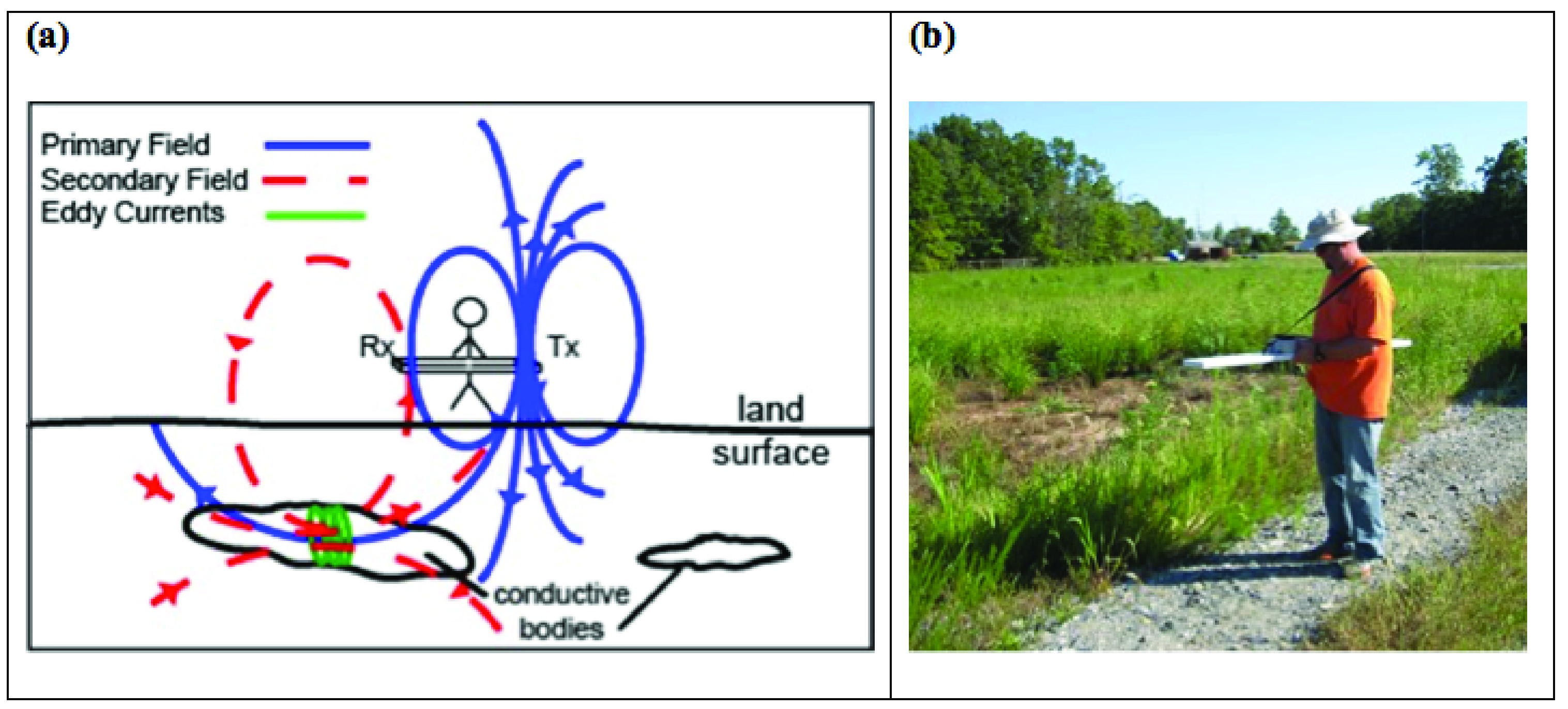 | 3,033 × 1,371 (2.69 MB) | Debra Tabron (talk | contribs) | Figure 2. Example of a surface-based geophysical method. (a) Schematic diagram of an electromagnetic induction tool in operation, which comprises a transmitter (Tx) and receiver (Rx) to respectively produce a primary electromagnetic field and measure a... |
- You cannot overwrite this file.
File usage
The following page links to this file: