File:Slater Intro Fig3.jpg
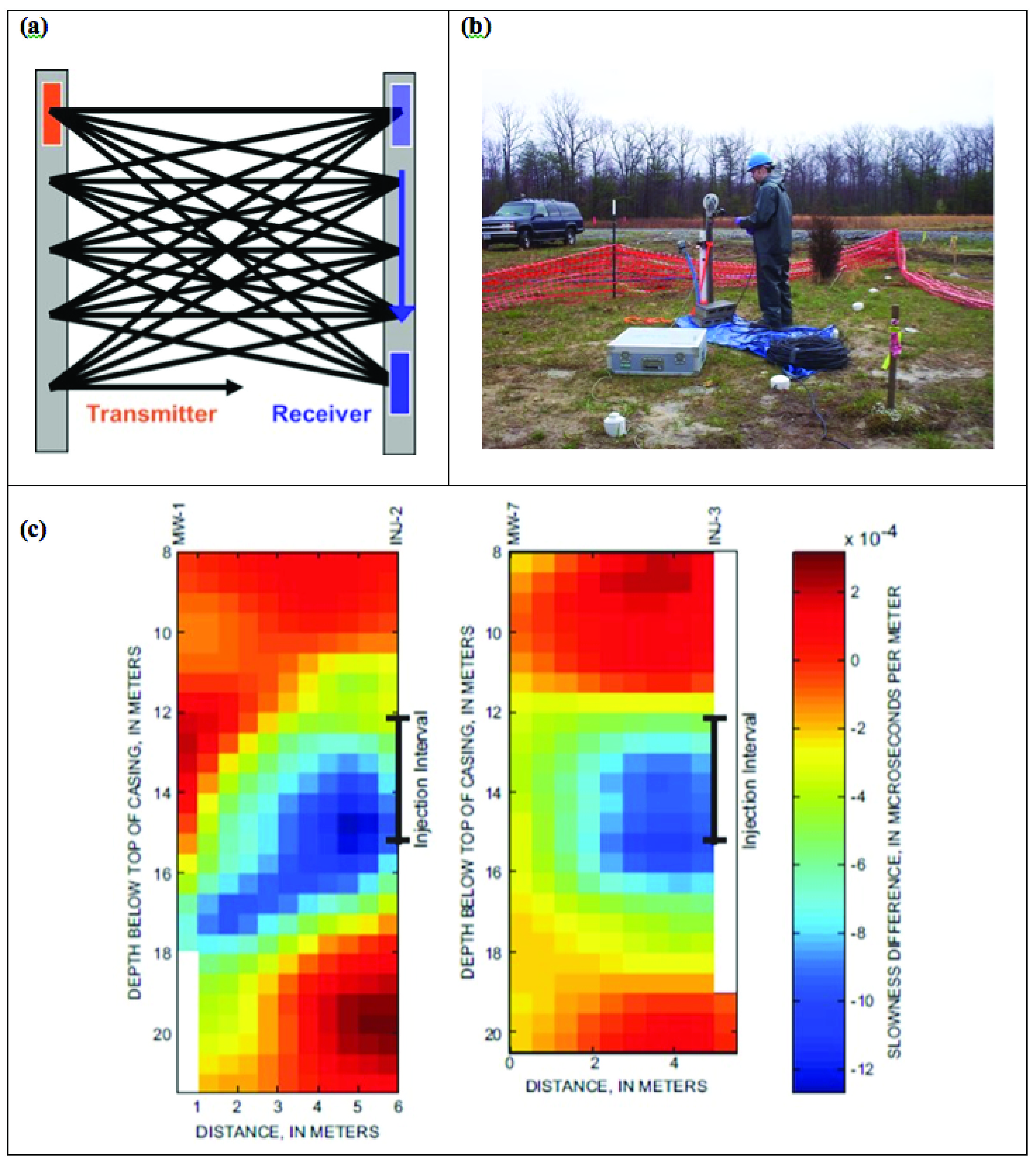
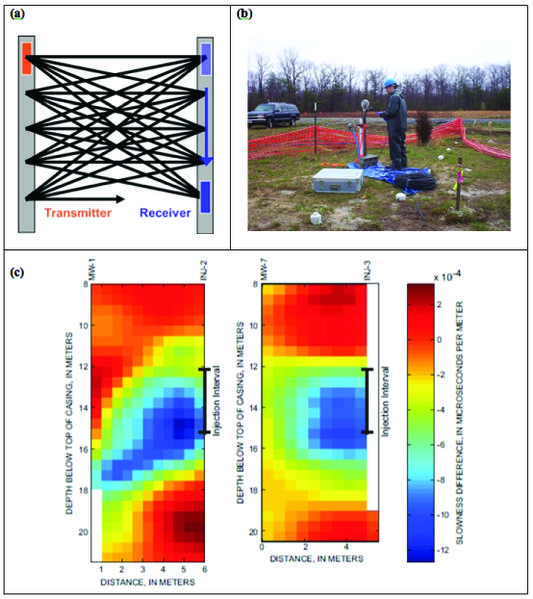
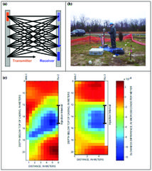
Figure 3. Example cross-borehole method. (a) Schematic crosshole radar tomography, in which a transmitting antenna is moved vertically in one well, and a receiver antenna is moved vertically in another well. High-frequency electromagnetic waves are transmitted through the interwell region, and received travel times and amplitudes are inverse modeled to produce cross sections of electromagnetic properties. (b) Photograph of data collection at a remediation site in Brandywine, MD. (c) Two radar tomograms from a remediation site in Fridley, MN, where radar was used to monitor emplacement of a vegetable oil emulsion (VOE) amendment which produces a negative change in slowness (1/velocity) relative to background conditions (after Lane et al., 2006.
File history
Click on a date/time to view the file as it appeared at that time.
| Date/Time | Thumbnail | Dimensions | User | Comment | |
|---|---|---|---|---|---|
| current | 15:23, 31 January 2017 | | 2,213 × 2,487 (3.25 MB) | Debra Tabron (talk | contribs) | Figure 3. Example cross-borehole method. (a) Schematic crosshole radar tomography, in which a transmitting antenna is moved vertically in one well, and a receiver antenna is moved vertically in another well. High-frequency electromagnetic waves are tra... |
- You cannot overwrite this file.
File usage
There are no pages that link to this file.